
[Updated 4th October 2021]
In this post, we will discuss the different types of transducers that can be used with the Prosig data acquisition systems and loggers. The post looks at the design and function of the different types of sensors and the applications they are normally associated with.
Accelerometers
An accelerometer is an instrument used to measure acceleration. It is normally attached directly to the surface of the test specimen. As the object moves, the accelerometer causes an electric current to flow, which is proportional to the acceleration. Acceleration and vibration are similar, but not the same. If a material or structure has a vibration, then it will be subject to certain accelerations. The frequency content and the magnitude of these accelerations is directly proportional to the vibration.

The main type of accelerometer is a piezoelectric type. The official name for these is IEPE, which stands for Integrated Electronic Piezo Electric. Often these are known as ICP, although that is actually a trademark owned by PCB. Because of the internal electronics of these sensors the acquisition equipment must include suitable power supplies and signal conditioning for the accelerometer.
IEPE transducers are usually based on quartz crystals and they would normally have the crystal mounted on a mass. As this mass and crystal are subject to an accelerative force a small voltage is induced across the crystal. This voltage is proportional to the acceleration.
There are also many other types of accelerometers on the market, capacitive types, piezoresistive, hall effect, magnetoresistive and the heat transfer type.
Accelerometers normally come in two distinct packages, side and top-mounted. The side-mounted package would have the interconnecting cable or connector on the side and the top-mounted package would have these on the top. Certain circumstances require different mounting methods. Accelerometers also normally come in one of two different types, single-axis and tri-axis. The single-axis accelerometer measures acceleration in one direction, whereas the tri-axial accelerometer will measure the acceleration in the classical 3-dimensional planes.

Mounting methods are very important for an accelerometer, it is normally best not to rely on just one attachment method from a safety point of view. The mounting method for an accelerometer is effectively an undamped spring and the frequency and magnitude effects of this spring on the frequency and magnitude of the vibration measurement must be considered. That is the reason that there is no single best attachment method for all cases. The most widely used attachment is a sticky wax, although super glue is also very popular. Both these have different frequency transmission characteristics, and their own advantages and disadvantages.
Accelerometers are probably the most widely used transducers in any investigation work on a structure of any kind. NVH (Noise, Vibration & Harshness) testing is just one of many fields that make use of them. If there is a requirement to find the frequency of vibration, for example, an accelerometer would be the obvious choice. It is important to make sure the frequency that is being investigated is within the usable range of the accelerometer. And that the maximum capable amplitude of the accelerometer is not exceeded at any point during the test.
Microphones
Microphones are used to measure variations in atmospheric pressure or indeed any other medium. Variations in pressure, which can be detected by the human ear, are considered sounds. Acoustics is the science behind the study of sound. Sound can be perceived to be pleasing to the ear or to be undesirable.
The human auditory system normally has a range of 20 to 20 kHz, although this range generally decreases with age. So sound pressure variations in that frequency range are considered to be detectable by the human ear. A microphone must be able to detect all of these frequencies and in some cases more. As sometimes sound pressure variations outside that frequency range can be important to design engineers as well.
The main types of microphones are the condenser microphone, carbon microphone, magnetic microphone and piezoelectric microphone. The condenser is the most widely used in situations where quality and accuracy are required. The condenser microphone is capacitive in its design. Its function is based on the transduction principle. There is a diaphragm that is exposed to the pressure changes this diaphragm moves in relation to the pressure fluctuations. Behind the diaphragm there is a metal plate, usually called a backplate. This backplate has a voltage applied across it and is effectively a capacitor. As the diaphragm moves closer or further away from the backplate the charge on the plate changes. These changes in charge are then converted to voltages.

A vibration can be considered to be a rapid motion of a particle or a fluctuation of a pressure level. NVH studies are concerned with the study of vibration and audible sounds. These studies focus on reducing the excitations and thus the amplitude of the sounds and reducing the transitions between large changes of frequency or shocks. Microphones are used in much wider fields however, in some cases microphones are used to acquire a sound, so that it can be amplified later. Microphones are generally used in any testing where the human auditory system would have an input. Environmental noise or inside an aircraft cabin for example.
Strain Gauges
A strain gauge is a sensor used for determining the amount of strain or change in dimensions in a material when stress is applied. When the sensor is stretched or strained its resistance changes.
The most common type of strain gauge is the foil gauge type. This is effectively an insulated flexible backing that has a foil pattern upon it. This foil pattern usually forms a 2 wire resistor. The gauge is attached to the structure under test by way of an adhesive. As the structure under test is deformed the foil is also deformed, this deformation causes the distance between the foil pattern lines to change. This change in turn affects the resistance of the gauge. In order to measure this very small change, the gauge is normally configured in a Wheatstone bridge.
Strain gauges are very sensitive to changes in temperature, to reduce the effect of this potential corruption a Wheatstone bridge is used with voltage supply sensing. This reduces the effect of temperature changes.
Strain gauges are also available as thin-film types and as semiconductor types. The thin-film types are used in higher temperature applications they are formed directly onto the surface of the structure, this has the additional advantage of not disrupting airflow in aerodynamic design. The semiconductor type gauges are referred to as piezoresistors. These gauges are used in preference to the resistive foil types when the strain is small. The piezoresistors are the most sensitive to temperature change and the most fragile strain gauge type.
Strain gauges are used in many disciplines of science and engineering, the classical use for strain gauges is in material and structural fatigue prediction, but strain gauges are used in areas as diverse as medicine & biology to aircraft & bridge design.
Torque Sensors
Torque measurement is the measurement of the angular tuning moment at a particular and instantaneous time in a shaft.
Torque is usually measured in one of two ways, either by sensing the actual shaft deflection caused by the shaft twisting or by measuring the effects of this deflection. It is then possible to deduce the torque in the shaft.
Classical torque sensors, normally based on strain gauges, are used to measure the deflection in a shaft. These gauges are mounted at 90 degrees to each other. One is mounted in parallel to the length of the shaft the other perpendicular to this.
Torque sensors, based on strain gauges as used in torque measurement, are often foil types, but can also be diffused semiconductor and thin-film types. However, any strain gauge based device will be subject to temperature variations. Unless this change, due to temperature, is sensed and accounted for then corruption of results can occur. To account for this bridge supply sensing is required.
There are also more modern types of torque transducer, these include inductive, capacitive or optical types. These types use a slightly different method to measure the torque. These styles of transducer tend to measure the angular displacement between two positions on a shaft and thus deduce the torque from this twist.
Torque transducers are used to measure many parameters such as the amount of power from an automotive engine, an electric motor, a turbine or any other rotating shaft. Recently torque sensors have been used increasingly as part of hand tools on a production line. This allows for the measurement of torque as screws or bolts are tightened on a production line, increasing greater quality control.
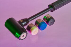
Impact Hammer
The function of an impact hammer is to deliver an impulsive force into a test specimen or material. The force gauge that is built into the hammer measures the magnitude and frequency content of this excitation.

An impact hammer is usually used in conjunction with at least one accelerometer. These accelerometers measure the response of the impulsive force in the material. And thus a transfer function can be deduced. It is possible to change the frequency characteristics of the impulse by changing the type of ‘tip’ on the head of the hammer. A harder tip will generally have a shorter response time and will be used for situations where higher frequency analysis is of interest.
Impact hammers, sometimes called modally tuned impact hammers, are normally controlled manually and often resemble a normal everyday hammer. They would be used in a classical structural or modal analysis situation, although they can also be used for acoustic testing. To use an impact hammer it is necessary to ‘hit’ the structure with the hammer. The weight and the type of hammerhead must be first correctly selected for the amount of force required to excite the structure. The bigger and heavier the structure the larger the hammerhead must be in terms of mass and in terms of force used.
The reason the impact hammer is often referred to as a modally tuned hammer is that the structural design of the hammer has been optimized so that the structural resonances of the hammer during the ‘hit’ will not affect the frequencies of interest in the structure and will therefore not corrupt the test data.
Impact hammers are used in many fields from automotive & aerospace R&D to bridge health assessment.
You can read more about impact hammer testing in this post.
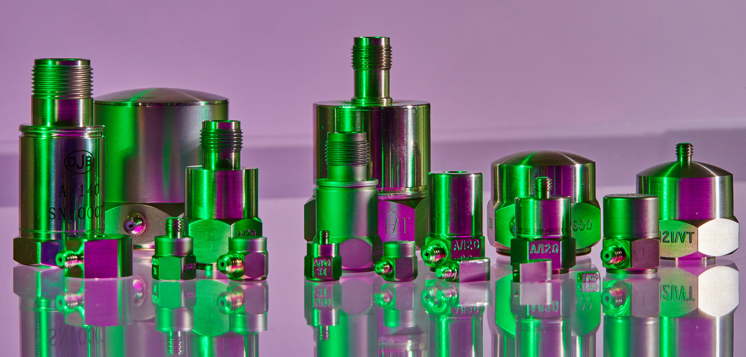
Pressure Transducers
Most pressure sensors used in industry today have a rather similar appearance. They normally consist of a cylindrical steel body with a pipe fitting on one end and a cable or connector on the other.
A pressure sensor is a transducer that converts pressure into an electrical signal. There are various types of these transducers on the market, but the most widely used is the strain gauge based transducer. The conversion from pressure into an electrical signal is achieved by the deformation of a diaphragm inside the transducer that has been instrumented with a strain gauge. It is then possible, knowing the relationship of pressure to diaphragm deformation, the sensitivity, to deduce the pressure.

Pressure sensors are used in any application where a gas or fluid pressure is being monitored. Sometimes this monitoring is over long periods, water pressure for example, sometimes it is for very short durations, for example, an automotive airbag.
Pressure sensors are normally a direct voltage output, however increasingly the IEPE constant current types are becoming standard. These types of sensors are used in situations where electromagnetic noise is present or when long cabling is required.
Force Transducer
A force transducer is a device for measuring the force exerted upon a particular structure. The force transducer measures the deflection in the structure that has been caused by the force, not usually the force itself.
However, some materials used in the construction of force transducers, when compressed, actually change in electrical characteristics. These materials do measure the force directly, they are active sensing elements and have a high-frequency response. They can however only normally withstand small amounts of force before damage occurs. The material in question is a quartz-based crystalline material. These are sometimes called piezoelectric crystal transducers. Electronic charges are formed in the crystal surface in proportion to the rate of change of that force being applied to the crystal. There are other types of force sensors available, for example, the ceramic capacitive type.
Typically these sensors are used for bench testing and for monitoring quality during reshaping or bonding operations on a production line.
Force transducers are heavily used in the aerospace industry, they are often used as part of pilot controls. It is important in these situations not just to have positional information on the pilot’s controls, but also the force being applied to the control system.
Load Cell
A load cell is basically a transducer that converts a load into an electronic signal. The majority of loads cells in the market are strain gauge based, however, there are some other alternatives. Almost any modern application that involves weighing uses a load cell compromising of strain gauges configured in a Wheatstone bridge.
Load cells based on strain gauges consist normally of four strain gauges bonded on to beam structure that deforms as weight or mass is applied to the load cell. As with most if not all cases strain gauges are used in a Wheatstone bridge configuration, as this offers the maximum sensitivity and temperature compensation. Two of the four gauges are usually used in tension and two in compression.
There are several ways in which load cells can operate internally by bending, shear, compression or tension. All of these types are based on strain gauges.
Less popular are the hydraulic load cell and the pneumatic load cell. The hydraulic load cell, as the name implies is based on fluid under pressure. As the pressure or weight on the cell changes a diaphragm is moved. These load cells are more commonly used in situations where temperature can be highly dynamic. Hydraulic load cells can be almost as accurate as the strain gauge based type. Pneumatic load cells operate on the force balance principle. They use multiple dampener chambers to provide higher accuracy than the hydraulic load cell. They would normally be used in situations where the mass being weighed is small, as they are not based on fluid they can be used in cleanroom environments. Additionally, they have a very high tolerance of variation in temperature.
Load cells are often used in automotive brake testing and development, the force applied to the pedal is compared to the force generated at the disk or drum, for example. The assist braking system can then be optimized for the expected use. It is possible to adjust the system so that for a given force on the pedal an appropriate force is generated at the brake pad to optimize the vehicle deceleration. Load cells are also used in such diverse areas as engine dynamometry, suspension spring testing, production line batch weighing and production line connector insertion force monitoring.
Thermocouples
A thermocouple is a sensor for measuring temperature. It normally consists of two dissimilar materials joined at one end that produces a small voltage at a given temperature proportional to the difference in temperature of the two materials.
Thermocouples are among the easiest temperature sensors to use and are used heavily in industry. They are based on the Seebeck effect that occurs in electrical conductors that undergo a temperature change along their length.
Thermocouples are available in different combinations of metals. The four most common types are the J, K, T and E types. Each has a different temperature range and is intended for use in a different environment.
Thermocouples are often used for temperature measurement of corrosive liquids or gasses, usually at high pressures. Thermocouples are used extensively in the steel and iron production industry, they are used to monitor temperatures through the manufacturing process. Because of their low cost, they are suitable for extreme environments where they have to be replaced often. They are a versatile transducer type and are probably the transducer used in most fields, from aerospace to cryogenic applications.
TEDS – Transducer Electronic Data Sheets
Transducer Electronic Data Sheet or TEDS for short, is a set of electronic data in a standardized format defined within the IEEE-P1451.4 standard. This data specifies what type of sensor is present, describes its interface, and gives technical information such as sensitivity, reference frequency, polarity and so on.
TEDS offers large benefits in that it simplifies troubleshooting, greatly reduces costs and removes the need for recalibration when changing or replacing sensors.
From the user’s point of view, when using a TEDS transducer, upon connection certain important fields are automatically uploaded from the transducer microprocessor and can then be filled in the test setup matrix. This can be very useful in the field. Further, when used in conjunction with a transducer database, all the fields in the test setup matrix will be automatically filled in upon transducer connection.
CAN-bus
Whilst not strictly a measurement transducer in its own right the CAN-bus is having an increasing impact on engineering measurement across a wide range of applications.
The Controller Area Network or CAN-bus for short is a multicast shared serial bus standard, originally developed in the 1980s by Robert Bosch GmbH. The bus is designed for use when connecting electronic control units. CAN was specifically designed to be robust in electromagnetically noisy environments and can utilize a differential balanced line like RS-485. It can be even more robust against noise if a twisted pair wire is used.
Many variations and developments of the original protocols have been devised. The current dominant systems are CAN 2.0 and CAN FD.
Although initially created for the automotive market, it is now used in many embedded control applications that may be subject to high levels of external noise. The use of the CAN bus continues to grow in all automotive sectors, and even in the aerospace sector. The Prosig measurement systems offer a dedicated CAN bus logger with dual CAN-bus inputs. This ensures that all CAN-bus data is captured along with any other data being measured. The Prosig system also supports both simple monitoring, where messages are read and logged from the bus, and PID mode, where automatic PIDs can be requested under user control.
Conclusion
All of the transducers and measurement systems in this article are supported by Prosig hardware. However, there are many other types of transducers not discussed here that can be used with the DATS-tetrad, DATS-solo and DATS-hyper12 systems. If you have other requirements please contact Prosig to discuss.
James Wren
Latest posts by James Wren (see all)
- What Are dB, Noise Floor & Dynamic Range? - January 12, 2024
- How Do I Upsample and Downsample My Data? - January 27, 2017
- What Are Vibration, Torsional Vibration & Shaft Twist? - November 8, 2016


Hi.
I want schematic of the complete analog signal conditioning circuit for a piezoelectric accelerometer for mpu base measuring.
Hello Ahmad,
Thanks for asking a question on our blog.
I would suggest contacting a transducer supplier normally, they may be able to advise further. But a good place to start would be a Sensor Article that I recently read that does in fact show a complete circuit diagram.
thanks for this rich explain on torque transducers.
I’m PhD student and I need to measure the torque transmitted to right and lift wheel by using strain gauges on each shaft connecting between differential and each wheel. without using torque transducers.
Do you can explain the correct direction for bonding the gauge and How I can measure the reading while it rotating.
thank you.
Hello Mohammed,
Thank you for asking a question on our blog.
Torque measurement is basically the measure of force being applied in turning a shaft. When a turning force is applied to a shaft the shaft twists by a very small amount. This twisting produces some deformation in the material of the shaft. This twisting is in a direction at 45 degrees to the axis of the shaft. The shaft effectively stretches slightly in that direction.
The shaft also exhibits a compressive force in the opposite 45 degree direction.
So if you mounted strain gauges at both +/- 45 degrees perpendicular to the shaft axis you should see both the compression and the extension forces.
With regards as to how to measure this whilst the shaft is moving is a more difficult question, it depends on the shaft itself and what you’re doing.
Generally we would use some wireless strain gauges for this application, but that might not be practical for your application.
hi,
In my lab we have an instrument that is very sensitive to any kind of noise/vibration and it is very important that any noise signal is avoided to get a good output. However, we always get an unwanted spike at 25 Hz and we are not able to trace the origin of this noise/vibration signal. can u suggest about any common sources? we used an accelerometer and checked at different places near the instrument and it always picks up the signal so I think its due to vibration… but the source is unknown…
Hello Swathi,
Thank you for asking a question on our blog.
This is most likely electrical interference rather than a vibration source you can’t locate. If you had said 50Hz was your problem I would have been convinced it was noise, as that is the usual electrical mains frequency and often a spike occurs at that frequency, perhaps there is a source of electrical noise at 25Hz in your laboratory.
I would suggest you consider that first, then second move the accelerometer to different places try to find where the spike is larger, then you’ll have some idea of the source.
If you just hold the accelerometer by its cable, so nothing can possibly effect it from a vibration point of view and you still see a 25Hz spike then it is definitely noise related, I’d suggest you look closely at your measurement equipment.
Please feel free to let us know how you get on.
Hi,
I was also looking for a schematic of the complete analog signal conditioning circuit for a piezoelectric accelerometer for mcu base measuring. I read your article but that schematic was not good…do you have it in pdf file or better condition?
Hello Adriano,
Thank you for asking a question on our blog.
The circuit diagram shown in this article is not intended for use, but for illustration purposes only.
You would not be able to use the above diagram for anything other than the basis of a circuit. You would need to consider many things, most importantly the amplifier gains if any, the ADC itself and may other parameters before you could finalise the design of a circuit.
I suspect this sort of circuit design would take quite some time, you may be better offer searching for an IC that does the entire job for you,