
 Knowing how to measure torsional vibration is of key importance in the area of vehicle development and refinement. The main contributory source is the engine where periodically occurring combustion cycles cause variation in the crankshaft rotary vibration. This vibration is transmitted to and modified further by other components in the powertrain such as the gearbox and by other equipment driven off the drive belt or chain. Additional torsional vibrations are also likely to appear downstream at the drive shafts and wheels.
The fundamental approach to analysing torsional vibration is to work in the angle domain rather than the time domain. This requires accurate measurement of the angular positions of shafts and gearwheels and involves instrumenting these components with tooth sensors, tachometers or laser sensors. Whichever type of instrumentation is used the fundamental output is the angular position of the rotating component as a function of time. In contrast to normal data acquisition applications where vibration signals are recorded at equispaced time intervals, for torsional applications the requirement is to measure the times of occurrence of equispaced angular positions.
Limitations of Conventional Data Acquisition Systems
Conventional data acquisition systems are limited in their precision by their maximum sampling rate – in some situations, they simply cannot sample fast enough to quantify an entity that is moving very quickly. The measurement of torsional vibration has two factors to take into consideration: the underlying circular motion and the rotary fluctuation superimposed on the circular motion. In fact, it is the fluctuation component that is usually of more importance to the vehicle analyst.
Consider the example of a signal from a shaft encoder that is outputting 1000 pulses per revolution at 6000 rpm. This is equivalent to
6000 * 1000 / 60 pulses /sec = 100,000 pulses /sec
Even with a system sampling at 400k samples/sec, this has an inherent positional error of 25% per pulse period. Increasing the sampling rate partially improves the situation but of course, this will also result in larger data sizes and unnecessary over-sampling at low pulse rates.
An improved method of Torsional Vibration measurement
A better approach to measuring pulse positions is to use a counter with a high-frequency clock to count the intervals between rising pulse edges. The equivalent sampling rate is now increased by approximately two orders of magnitude. The DATS Advanced Tachometer Module (Type 8×20) for Prosig’s DATS-tetrad and DATS-hyper12 systems operates at 240 MHz which gives an effective resolution of 4.167 nanoseconds (1 ns = 10-9 secs). In the context of the example above this now results in a positional error (of pulse duration) of less than 0.05%.
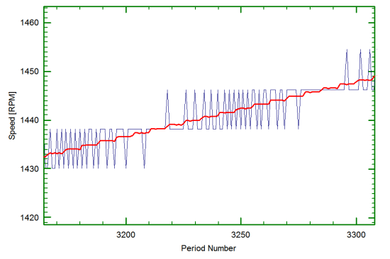
The differences between the Advanced Tacho measurement and a Standard Tacho measurement can be seen in the graph. The blue trace was from a signal sampled using a conventional equal-time based system and the red trace was the same signal sampled using a pulse-edge measurement system based on a high-frequency clock and counter. The input signal was a stepped-sine sweep whose discrete steps can clearly be seen in the red trace. The fluctuating nature of the blue trace indicates the degree of uncertainty and inaccuracy of the conventional method of capturing tacho signals.
Analysis methods for Torsional Vibration
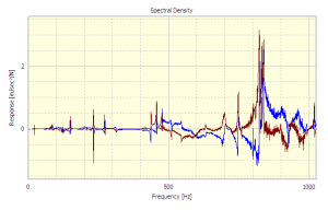
One of the advantages of working in the angle domain is that spectral analysis of the pulse periods produces order waterfalls and order spectra directly without recourse to interpolated resampling.
Adrian Lincoln
Latest posts by Adrian Lincoln (see all)
- Averaging Frequency Response Functions From A Structure - June 17, 2016
- Seismic Qualification Testing (Part 1) - June 14, 2016
- What is Operating Deflection Shape (ODS) Analysis? - September 1, 2014


I am interested to find out how do you account for Gear mechanical runout during the torsional analysis? As you know mechanical runout will show as first torsional order (1X)
Thank you
ID
We would not expect to find (first order) runout in torsional analysis when using conventional tachometer instrumentation (such as shaft encoders or hall-effect probes) because they only sense angular motion not radial motion.
Adrian
I red a published paper (some time ago) by Scientific Atlanta in which they were ademant about the run out compensation especialy when, for example, the readings are taken from large Diesel engine flywheel starting gear due to the “big” diameter? The signal was acquired from permanently instaled magnetic probe used for RPM tacho….
We are going to repower a Tug boat and looking for Torsional Vibration Analysis for new C18 engine with old trans line. Would you offer your software for that kind of calculation?
Thank you in advanse,
Arkadiy
Hello Arkadiy,
Thank you for asking a question.
Your application is very interesting but it is outside of the scope of this article. We will contact you directly to discuss in more detail.
Hello James,
I am looking for a software to perform torsional vibration analysis of a mass elastic system ( engine + coupling elastic + pump). Does your software do such calculation?
Thanks,
Ademar.
I would like to invite you if u have any videos of your equipment to contact me and post free to my Machines Video blog
http://machinesvideo.blogspot.com
thanks!
Hello Mr. Lincoln,
I read about your article. I am currently doing a project, on the business & marketing side, on torsional vibration analysis. I really have a very limited knowledge on it so I want to know where can I use torsional vibration analysis apart from Motors and gearboxes. It is said that it can be used to any machine that rotates, could you perhaps provide me an example of other possible machine?
Best Regards,
Jasmin
On the subject of using angular measurments on a 2000 HP Waukesha Gasious fired cogeneration engine.A high displacement by a connecting rod was found to have been occuring within the burn angle.I found this to be attributed to high Intake Manifold Pressure as a result of the turbocharger control managment system attempting to compensate for lower than required BTU/SCF on digester gas.This can result in connecting rods being tossed through the crankcase if left unchecked.Just passing along an experience with angular measurements relative to an Internal Combustion Engine Cycle.
Hi John
Thanks for the comment. That is the sort of real-world information that can prove invaluable to the right person at the right time. And it’s one of the reasons we put time and effort into the Noise & Vibration Blog!
Dear sirs, I am very interested in monitoring torsional vibrations in a vertical mill for a cement industrie. This monitoring must be a permanent monitoring, and I have though to use strain gauges to carry out torsional deformations and to use telemetrie to acquire this type of signals. Could it be your system adecquate as an option for this application? Please answer me privately to my e-mail. Thank you very much in advance.
I read about the article. I am currently doing a project on torsional vibration measurement using strain gages.what is the relationship of strain and torsional vibration ?
One of the issues here (from the initial example) is that you only end up with as many samples-per-rev in your output data as you have teeth on your ring-gear. Add to that the fact that the gear is usually used for something (such as a starter motor) and has physical nonuniformity of the spacing between the teeth due to uneven gear wear which results in a fluctuating count being recorded even under purely constant speed rotation circumstance. (Diesel engines for example usually engage the starter motor in one of two regions of the ring gear the hardest as they stop where the compression is greatest). So to do this accurately then requires a “Mask” be made which characterises these geometric errors on the gear, and which can later be used to compensate for this. A better solution involves the use of a precision shaft encoder (say 720 pulses per rev, giving 0.5 degree resolution ) to get rid of this effect and add angular resolution.
Thanks for sharing such useful information with us.Please keep sharing more!
Thanks for your comments, John. It is worth pointing out that the Advanced Tachometer module referred to in the article has been improved still further and now operates at 240MHz which is four times faster than the original module.
Does the Prosig P8000 series use angle domain method ? I mean any speed fluctuations is captured in terms of radians during an event of torsional ocsillation?
Thank you for your question Mantosh.
The Prosig Advanced Tacho module measures the time between pulses from an encoder or sensor using an accurate counter-timer running at 240 MHz.
These pulses will be spaced at equal angles, so in effect the system measures angular velocity in terms of degrees per second which can easily be converted into radians per second. The more pulses per revolution there are, the more accurate the angular velocity measurement will be, because it will be able to detect small changes in velocity that may occur within one revolution. This is important both for angular vibration measurement on a single shaft or gear, or transmission error calculations between two shafts or gears.
Could the same signal processing technique be applied using Motor current signature analysis ?