
At least one manufacturer of data acquisition systems claims to achieve an incredibly high dynamic range (160dB) when capturing data. This is supposedly achieved by the use of dual-range data acquisition architecture. Such systems have two analog-to-digital convertors for each input channel; one of the ADCs captures the full voltage range of the input signal and the other ADC captures the input signal only when it is small. This article explains the facts behind the figures and shows that the use of Dynamic Range as a measure of precision can be misleading.
Quantisation, Bits and Dynamic Range
All data capture devices suffer from noise contamination due to the quantisation process that takes a continuously varying voltage signal and represents it digitally as a series of discrete amplitudes that change at discrete moments in time. The effects of quantisation noise can be reduced either by sampling more quickly or by increasing the number of discrete levels that are used to approximate the true voltage. The number of levels is usually expressed in terms of the length of the digital word that represents the largest amplitude. Digital word lengths are defined by the number of “bits” (binary digits) that they contain, for example 8-bit, 16-bit, 32-bit and so on, where each bit represents a doubling of digital amplitude (1,2,4,8,16….). For example, an 8-bit digital word encompasses all numbers in the range 0 to 255 (the highest number is 2n-1, where n is the number of bits). The concept of “doubling per bit” leads to an expression for the Dynamic Range of a digital word in terms of the ratio of the highest number to the smallest number that it can represent expressed as a dB value. 6dB corresponds to a doubling of amplitude (for each bit).
Dynamic Range (dB) = 20.0 log10 (Largest number/Smallest Number)
It is usual to approximate the largest number by 2n rather than 2n-1, which allows the expression to be simplified as follows:
Dynamic Range (dB) = n * 20.0 log10 (2.0) = 6n dB
So, for a modern 24-bit ADC the theoretical dynamic range is 6 * 24 = 144 dB.
Amplitude Resolution and Quantisation Noise
The bit length of a digital word determines the step size between adjacent quantisation levels. For example, if an ADC has a word length of 8 bits then for a unipolar input range of 10 Volts, the step size will be 10.0/(28-1) = 10.0/255 = 39.216 mV. This is also the smallest voltage that can be measured with such a device (in the absence of any electrical noise). If, however, the number of available bits increases to 16, then the smallest voltage reduces to 10.0/(216-1) = 10.0/65535 = 0.153 mV. More usually ADCs operate over a bipolar range of 20V peak to peak, so in this case the smallest voltage would be 20.0/65535 = 0.305mV.
If the amplitude of the signal being quantised varies over a wide voltage range then the effects of quantisation are relatively small. Take for example the spectrum of a 1 KHz sinewave of amplitude 2 volts peak to peak. A comparison of the spectrum of the true (continuous) waveform and the equivalent spectrum of the digitised (24-bit) waveform are shown in Figure 1 below. The dramatic increase in the noise floor of the digitised waveform is clear to see; the noise floor in the case of the pure sinewave is about -300dB, but for the digitised version it is about -150dB.

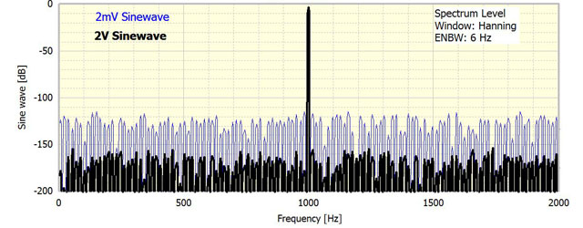
For smaller amplitude sinewaves the noise floor increases as the effective number of quantisation levels decreases. See Figure 2 below for the corresponding (normalised) spectra for a sinewave of 20mV (peak to peak) digitised with a 24 bit ADC having a 20 volt range and the corresponding 2V (peak to peak) sinewave shown previously.
To simplify comparisons the signals were normalised such that their peaks gave the same dB level. The smaller of the two signals has the higher noise floor and illustrates well the problem of having fewer effective quantisation levels. For systems that do not have analogue gain in front of the ADC the quantisation noise will affect the accuracy of the analysis of any waveform that does not utilise the full input voltage range of the ADC. Prosig P8000 Data Acquisition Systems do have front-end amplifiers and can therefore optimise the voltage range to match the ADC. Prosig systems support gains of up to 1000; this means that the ADCs can be set to capture signals as small as +/- 10mV without reducing the number of quantisation levels and thereby avoid the problems illustrated in Figure 2. The effect of the additional gain is to add a static range of 60dB on top of the theoretical dynamic range of 144dB of the 24bit ADC.

Static Range Control
The choice of optimal range setting can be partially addressed by letting the system choose the best range to suit the data (after a trial capture). In the case of Prosig P8000 data acquisition systems there is wide range of gains available for the system to use. The main limitation of any auto-ranging system is that it can only optimise to the highest amplitude present in the data, it cannot adjust the range continuously throughout the duration of the time history.
Dual Range Systems
To some extent the problem of insufficient quantisation levels at small amplitudes has been partly addressed by systems such as the one illustrated below which employs a dual-range measurement strategy. This type of system is designed primarily to avoid the user having to perform manual range switching, not to provide better accuracy or higher dynamic range. The incoming signal is fed to two independent, synchronised ADCs, one of which is preceded by a fixed gain amplifier that boosts low level signals prior to digitisation. For discussion purposes assume that this amplifier supplies 36dB of gain (equivalent to 6 bits) and that there is an amplitude limiter (clipper) in front of the amplifier to avoid overload saturation.
There are three points to be aware of. First, if the input signal is always smaller than +/- 158.49 mV (corresponding to -36dB relative to full scale) then it never uses the gain-less ADC, so in this case the system has no advantage over other similar 24bit data acquisition systems. In fact it is inferior to standard Prosig P8000 hardware because the P8000 has programmable ranges down to +/- 10 mV (equivalent to a gain of 1000 or 60dB); in other words the resolution of the P8000 is better by 24dB for signals that are smaller than 10mV.

After capture the smaller signal is attenuated digitally back to its true level and then “combined” with the larger signal using a DSP switcher. In general when the incoming signal is led than 312.5 mV then the DSP will use the amplified version of the signal in preference to the unamplified one.
Second, for any data point greater than +/- 158.49 mV the ‘lower’ ADC with the 36dB gain amplifier will limit and so cannot be used. For signals that cross the 158.49 mV threshold the DSP Data Switcher selects either the value from the ‘upper’ ADC or the ‘lower’ ADC on a point-by-point basis. This method reduces the overall noise because the low voltage parts of the signal are better defined and it potentially enhances the dynamic range. However, the noise floor will still be dominated by the values digitised by the ‘upper’ ADC.
Third, if the input waveform contains signal components of more than one frequency and the amplitude of at least one of those components is greater than 158.49, then the dual-range system cannot achieve the claimed dynamic range of 160dB because for part of the time it has to use the high input ADC (range +/- 10Volts) which is limited to a theoretical maximum of 24 bits of digitisation (144dB) – and that is only achievable when there are zero noise contributions from both the transducer and the measurement electronics, which is virtually impossible. In practice 2 or more bits of resolution will be lost to unavoidable noise contamination, so even 144dB is not achievable under normal conditions.
A dual-range system is, however, good for capturing transient signals that contain both high and low amplitudes, but it offers no advantage for capturing signals (of any type) whose peak amplitudes are smaller than 158.49 mV. The claims made by some manufacturers of dual range systems with respect to the dynamic range being 160dB (when using narrow band spectral analysis) are somewhat misleading and may be misinterpreted. By using narrow frequency bands it is possible to obtain better signal to noise ratio. This is based upon the assumption that the noise has a uniform, white spectral density (measured in Volt2/Hz). So if the analysis uses a narrow frequency band then the power in a sinewave signal remains constant but the noise in the narrow band reduces giving a better narrow band signal-to-noise ratio or dynamic range. The true performance can only be assessed using wide-band analysis.
Conclusions
Although dual-range systems can measure both large signals (close to full-scale) and small signals (close to zero) they cannot accurately measure large signals that have small fluctuations superimposed on them, such as broadband signals or narrowband signals with low amplitude harmonics. In this respect the use of Dynamic Range to qualify the “accuracy” of a data acquisition system is misleading – a better measure would be Amplitude Resolution expressed in Volts because in the case of dual-range ADC systems the manufacturer would have to state two different resolutions and thereby make it clear that they cannot achieve high precision over the whole voltage range.
Adrian Lincoln
Latest posts by Adrian Lincoln (see all)
- Averaging Frequency Response Functions From A Structure - June 17, 2016
- Seismic Qualification Testing (Part 1) - June 14, 2016
- What is Operating Deflection Shape (ODS) Analysis? - September 1, 2014


the dynamic range is the ratio of the highest signal component to the lowest component that a system can measure (identify) at the same time . In that case dual-range does not help.
Further, most of the sensors have a dynamic range of (much) less than 100 dB, so this debate is more an academic one! And last but not least the “noise” of the process itself, aka signal components which are not related to the physical quantity to be measured are most of the time in the order of at least -100 dB.
Thank you for your comments Alain, I agree entirely. (I probably should have mentioned the poor dynamic range of most sensors as well). The problem we often find with customers who are unfamiliar with data acquisition systems is that they only judge equipment by the specifications in the data sheets and on paper 160dB always sounds better than say 110dB. So, all the time we have to convince these people that the quoted figures are misleading except for very specific types of data (such as pyrotechnic shock data and closed loop control sinewave data), but even here the noise floor of the transducers dictates the achievable dynamic range.
There are several more issues that arise when we are talking about dynamic range. Alain Weiler’s comment is certainly correct for the classical definition of dynamic range. For some tests, discriminating small signals in the presence of large ones is the objective. However, for a large number of tests the noise floor, relative to full scale, is the critical parameter.
These tests are ones where the outcome is very uncertain and/or there is a lot of out-of-band energy (explosive tests are a good example that exhibit both problems). In these cases it is important to set the measurement full scale to a large multiple of the expected result. I use the term headroom to quantify this ratio. I have seen tests where a headroom of 100 or more is appropriate (discussion of these might be a side conversation).
If we use a headroom of 100 and want to measure a signal to within 1% this requires a noise floor that is at least a factor of 10,000 (80dB) below full scale FOR THE FULL SIGNAL TRAIN. This is a tall order but it can be accomplished with the right kind of transducers (IEPE for example), good wiring practice (twisted-shielded pair), good signal conditioning, and a high-quality data acquisition system.
Some vendors claim that their transducers are good enough to warrant the use of dual-range systems but I have not seen it demonstrated in a realistic environment. For most of us, a good 16 bit system is adequate.
Another issue is the use of dynamic range characterized in spectral vs. time domain. Spectral characterization will always produce a higher dynamic range in (approximate) accordance with the equation:
Spectral Dynamic Range (dB)=Time Domain Dynamic Range + 10 log (N/2)
where N is the Fourier Transform block size.
I just ran across this article after reading the sales pitch on the Dyn-X 2-ADC (dual-range) system. The term “dynamic range” is certainly being used in a non-standard way to assert 160 dB! The “dynamic range” that is key is SFDR (Spurious Free Dynamic Range). Digitize two equal amplitude tones that produce a time domain waveform that peaks 1 dB under full scale. Do a very large Fourier transform on a large block of data where both tones are at zero on one end of the block of data, and both tones are one point away from being at zero on the other end of the block of data. After the transform, note how many dB all the spurious signals are down relative to the amplitude of the original tones. If the block of data is large (i.e. large enough that the spurious terms poke out 10 dB or more above the noise), this SFDR number will NOT depend on the size of the block of data. This SFDR number represents the limit in how much you can suppress/reduce the “noise & distortion” regardless of how much averaging (or signal integration) you might do. Normally the ADC is digitizing a complex signal environment, and all these spurious terms simply become the “noise floor”.
The “spectral dynamic range” Strether talks about is a metric that assumes that the amplifiers and ADC are ideal (i.e. perfectly linear). It allows the “Spectral Dynamic Range” to go to infinity as the block size goes to infinity, since the frequency bin bandwidth is going to zero. In practice, it’s not very useful, not only because it depends on the block size (or bandwidth), but because nonlinearities dominate in real data. Since the SFDR captures the effect of the nonlinearities, it is a far more useful metric to compare ADC performance. And as you point out, a dual-range ADC, where each has a 110 dB SFDR, and simply switching between them, will never get an SFDR better than 110 dB. So long marvelous looking 160 dB!
let the dynamic range be 20V.what is the maximum value of quantisation error when the word length is 2,4,6,8 or 16 bits.
What is the answer of this question.
Pingback: What is noise floor? What are dB? What is Dynamic Range?