

We are often asked about AC and DC coupling. This is important to understand when working in the signal processing field.
In terms of AC and DC Coupling, what is Coupling?
Quite simply, coupling is the transfer of energy from one medium to another, for example, from a metallic wire to an optical cable. This transfer of energy may be desirable or undesirable.
DC coupling allows both AC (alternating current) and DC (direct current) signals to pass through a connection.
AC coupling allows only AC signals to pass through a connection.
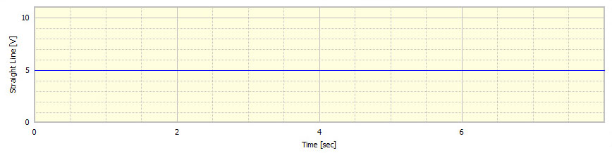
A DC source can be considered to be like a battery, in that there is a constant negative charge from the battery’s negative terminal to the positive terminal. An example of such a source is shown in Figure 1.
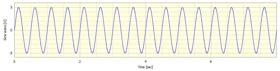
An AC source is one that is constantly changing from positive to negative. A sine wave is an example of an AC signal, such as the one shown in Figure 2.
DC coupling effectively does nothing. It does not affect the signal at all; everything that goes in comes out again.
AC coupling will remove the DC component from a signal.
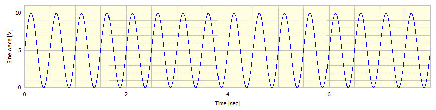
For example, a sine wave with a mean of zero and an amplitude of +/-5 volts, as shown in Figure 2, would be unaffected by both AC and DC coupling. But a sine wave with a mean of 5 volts and an amplitude of +/-5 volts would be affected by an AC coupling but not a DC coupling. The example shown in Figure 3, when passed through a DC coupled connection would be unaffected. But if the signal shown in Figure 3 were to be passed through an AC coupled connection, the 5 volt mean content would be removed and the signal would match that shown in Figure 2.
So AC coupling rejects the DC component of the signal. Effectively, this normalizes the signal to a zero mean.
The DC component of a signal can be considered to be 0Hz and any AC component of a signal to be above 0Hz. For example, an AC coupling filter might have a cut off frequency of 1 Hz. Therefore, passing a signal through this AC coupling filter would result in the frequency content of the signal below 1Hz being removed.
James Wren
Latest posts by James Wren (see all)
- What Are dB, Noise Floor & Dynamic Range? - January 12, 2024
- How Do I Upsample and Downsample My Data? - January 27, 2017
- What Are Vibration, Torsional Vibration & Shaft Twist? - November 8, 2016


What a simple way to understand the terminologies! keep it up James!
the art of expalining seamingly difficult concepts in a clear and understandable way is a teaching skill that Prosig masters and exells in.
Kudo’s to the Prosig team.
Georges Otte
thanks to give such good information………………in very simple way.
The terms AC/DC to define the characteristics of signals seems antiquated terms from the days of Tesla snd Edison.
First the idea that, in the world of instrumentation, the measurement of current is common is rediculous.
Maybe we should change it to AV/DV to align with instrumentation requirements.
Second the term direct is not an intuitive definition of the concept while alternating is much more intuitive. Maybe call it non-alternating or static(ok that does not work for obvious reasons) or persistant or constant (etc).
So lets start a new trend of calling it AV/CV.
Someone will have to inform the band.
Hi Jeremy,
Thank you for posting to our blog.
I understand your points and I think they are valid to make, if or when other people in the world will understand or adopt ‘our’ new system I don’t know, but we could at least try.
James, After I sent the note I realized that this was a general rant about the concepts of AC/DC (AV/CV) versus a comment about coupling. The discussion around coupling was useful but did not cover any thing about Prosig specific stuff like frequency cutoff and useful values of it.
Hi Jeremy,
Thanks for posting on our blog again.
Generally speaking we try to keep these articles educational rather than specific to our products, it is not always possible, but we do try.
You may find more useful material that is Prosig specific on our support blog, which you can find here http://support.prosig.com/
There is a specific article, How To Choose A Sample Rate For A Required Analysis Frequency Range which you may find useful.
If you have a suggestion for a subject you’d like to see discussed, please feel free to propose it.
Leave James alone. There are some old and antequated folks (ME) that are still learning and I really appreciate explanations that I can understand.
Thank you James and don’t forget the old folks.
Hi Ken,
Thanks for posting on our blog, and thank you for your warm comments, it is appreciated to know that what we do here is helping people.
We’ll try to keep the articles flowing as best we can for you.
excellent explaination..!
Hi Pragya,
Thank you for your comments, we will continue as best we can to provide further information for you and our readers.
Very often things are simple, but often people just can’t explain/ teach those things in a simple way, so that they seems to be very difficult.
Thank you , James.
Hi Ben,
Thank you for your comments, we do try our best, but it is very nice to hear that you have found our work useful, thank you very much!
you are doing a great job of explaining technical terms in clear and simple terms. Thank you!
Hi Paul,
Thank you for posting on our blog.
We warmly appreciate your positive comments, thank you.
We will keep trying to do our best!
thanks a lot! what a helpful! i’m happy
Hi JH,
Thank you for posting on our blog, I’m glad to read that you have found the article helpful and useful. Our objective here at Prosig is to provide as much information to the wider engineering community as possible.
If you have suggestions for other subject matter, please feel free to make a suggestion.
Hi James,
This posting is very informative for amatuers like me trying to understand AC and DC coupling, but the 3rd figure cannot be clicked for an enlarged image to see how a sine wave with a mean of 5 volts and an amplitude of +/-5 volts would look like and to understand how it would be affected by an AC coupling by comparing images 2 and 3 we could understand it better from illustration. Also it would be nice if a post on differential net is made in an understandable manner.
Dear George, thanks for spotting that. Figure 3 is now clickable. Apologies for the error.
Hello George,
Thank you for posting on our blog.
I believe the issue with figure 3 has now been addressed.
I do not understand the second part of your post, differential net?
Could you expand further please?
Pingback: Ki?n th?c c? b?n, m?ch và ?ng d?ng c?a b? khu?ch ??i ho?t ??ng (op amp) - FaqDesk - General information site about technology knowledge, articles on Blogspot tips, computer tips,...