
Assuming one wants a frequency spectrum from an acquired time measurement, it is generally accepted that averaging of a signal in the time domain is not very useful due to the randomness of the start of the time block used to calculate the Fourier transforms to be averaged. If there is a way to synchronize the start of the time block to a periodic event in the signal, then averaging in the time domain is possible and can be very useful.
Example
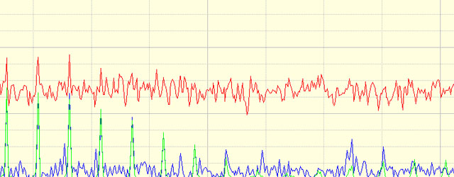
To demonstrate the usefulness of averaging time signals, a random time signal and a pulse time signal are generated and summed.


When the time signal of the pulse is embedded into the time signal of the random signal, the pulse signal becomes totally indistinguishable in the time domain and only barely distinguishable in the frequency domain figure.


The Process
As seen in the figures above, finding the spectrum of the pulse signal does not yield much usable information even when averaging of the spectrum is performed. The question is, how can the “noise” (random signal) be minimized so that the spectrum of the pulse can be seen?
Time domain signal averaging is only applicable if the signal is stationary (in the statistical sense). If the start points of the analysis time blocks are synchronized to the pulse, these time blocks will be random with respect to the random signal. Consequently the components of the signal uncorrelated to the pulse data will average towards zero.
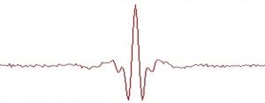
Once all the time averaging is completed, the pulse signal or any signal correlated to the pulse signal should remain and any uncorrelated signals should average towards zero. The results of the time averaging of the above signals are shown in figures 7 & 8.


Possible applications
It is reasonable to ask how this be used in real world. Time domain synchronous averaging is most applicable to situations when measurements are being made on constant speed rotating machinery in very noisy environments. To evaluate the vibration from a motor or gearbox which are engulfed in an environment of high levels of uncorrelated noise. This might be a motor/gearbox driving a tumbler used for mixing or polishing. An automotive applications could include the desire to extract the powertrain noise or vibration signals while driving over a very rough surface. Any application where the desired signals are correlated to a trigger signal from the test specimen has a potential for making this a viable method of extracting the desired signals.
John Mathey
Latest posts by John Mathey (see all)
- Exhaust Vibration Measurement – A Case Study - March 11, 2016
- What Is Amplitude Quantization Error? - January 27, 2016
- Creating An End of Line Vibration Test System - February 25, 2015


This is a first class description of a very useful technique. I have been using time synchronous averaging in vibration troubleshooting, since 1979, with various 1, 2 & 4 channel RTA’s. Readers may be interested in another application for sync time averaging: 2-pole electric motor vibration analysis, in distinguishing 2xRPM (slightly less than 120 Hz), 2x Line Frequency (~120 Hz), and Ball Spin Frequency (often very close to 2x rpm). It is usually an easy task to synchronize analyzer acquisition with 1xRPM, hence dropping out electrical and anti friction bearing vibration, and identifying 2xRPM mechanical (misalignment, looseness, impacting, etc.) vibration. It may not be so easy to sync with LIne Frequency (~60Hz), but it can be done, thus clearly identifying any 120 Hz “electrical” vibration. If a small (0.02 ips pk) third frequency remains, close to 2xRPM, it may be Ball Spin Frequency, and considered potentially serious.
Stuart,
It is gratifying to hear our articles on the PROSIG blog are appreciated.
Your comments on using synchronous averaging to separate mechanical vibration from electrical vibration in 2-pole electric motors is very useful information and very much appreciated. Hopefully others can use this valuable information.
Best Regards,
John Mathey