Calculating Velocity Or Displacement From Acceleration Time Histories

It is quite straightforward to apply “classical” integration techniques to calculate either a velocity time history from an acceleration time history or the corresponding displacement time history from a velocity time history. The standard method is to calculate the area under the curve of the appropriate trace. If the curve follows a known deterministic function then a numerically exact solution can be found; if it follows a non-deterministic function then an approximate solution can be found by using numerical integration techniques such as rectangular or trapezoidal integration. Measured or digitized data falls in to the latter category. However, if the data contains even a small amount of low frequency or DC offset components then these can often lead to misleading (although numerically correct) results. The problem is not caused by loss of information inherent in the digitisation process; neither is it due to the effects of amplitude or time quantisation; it is in fact a characteristic of integrated trigonometric functions that their amplitudes increase with decreasing frequency.

Continue ReadingCalculating Velocity Or Displacement From Acceleration Time Histories

Evaluating A Closed Loop Control System For High Pressure Pumps

Prosig were recently involved in the validation of a closed loop control system for an automotive pump supplier. The customer has a large number of test cells, each test cell has 8 pumps continually on test. Each pump is instrumented with a revolution or tachometer sensor, giving a once per revolution tachometer pulse. Additionally, there are various analogue transducers on each pump which measure parameters, such as pressure at the pump inlet and outlet.

(more…)

Continue ReadingEvaluating A Closed Loop Control System For High Pressure Pumps

Measuring Torsional Twist & Vibration Along a Shaft or Through a Geartrain

The measurement of torsional twist, or the twist angle, between two points along a shaft or through a gear train may be derived from a pair of tacho signals, one at each end of the shaft. Typically the tacho signals would be derived from gear teeth giving a known number of pulses/revolution. For example one end of a shaft could have a gear wheel with say 60 teeth giving 60 pulses/revolutions when measured with say an inductive or eddy current probe. (more…)

Continue ReadingMeasuring Torsional Twist & Vibration Along a Shaft or Through a Geartrain

High Pass Filtering And Tacho Signals

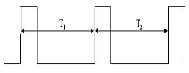
It is sometimes necessary to perform high pass filtering to eliminate low frequency signals. These may arise for instance from whole body vibrations when perhaps our interest is in higher frequency components from a substructure such as an engine or gearbox mounting. The vibration levels are speed sensitive and the usual scheme is to record a once per revolution ‘tacho’ signal with the vibration data. The tacho signal, which ideally is a nice regular pulse train, is processed to find rotational speed and hence to select which part of the vibration signal is to be frequency analyzed. The most common form of analysis is a waterfall type such as shown below.

(more…)

Continue ReadingHigh Pass Filtering And Tacho Signals