It is sometimes necessary to perform high pass filtering to eliminate low frequency signals. These may arise for instance from whole body vibrations when perhaps our interest is in higher frequency components from a substructure such as an engine or gearbox mounting. The vibration levels are speed sensitive and the usual scheme is to record a once per revolution ‘tacho’ signal with the vibration data. The tacho signal, which ideally is a nice regular pulse train, is processed to find rotational speed and hence to select which part of the vibration signal is to be frequency analyzed. The most common form of analysis is a waterfall type such as shown below.

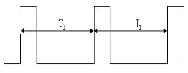
Suppose now we need to eliminate the low frequencies. This is quite simple as all we need to do is to perform high pass filtering on the vibration data. Because normal filtering causes a time delay then we must also filter the tacho signal. Conventional wisdom is that if all signals are filtered the same way then the effects of time delays may be ignored as they are all the same relatively. This, however, ignores the time domain effect on the signals, which is important for tacho signals.Processing a tacho signal is essentially based on determining the time interval between successive rising edges as illustrated for the ideal tacho shown below.

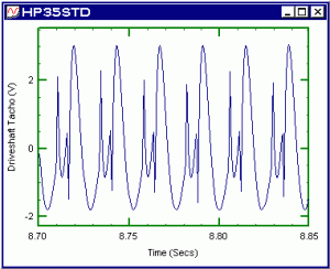
If each pulse represents one revolution then the speed between the two successive pulses is clearly (1/T). A real tacho pulse is rarely as clean as above. The figure below is a typical tacho signal measurement. In fact, as far as tachos go the example is quite a good quality tacho.

Because of the effects of noise we need to choose a threshold amplitude level as our trigger point to determine the time interval between successive pulses. If the tacho goes between Vmin and Vmax then generally a suitable threshold level is (Vmax+Vmin)/2.

Suppose now we need to high pass filter our data to eliminate some low frequency characteristics. Applying the same filter to the tacho may cause some dramatic effects. The example below is the tacho signal above filtered with a simple 4 pole high pass Butterworth filter set at 5Hz. This is a well behaved non aggressive filter but its effects on the tacho waveform are quite significant.

Whilst we have the same average temporal delays the detail effects are such that we may run into serious difficulties in selecting a trigger point. It could be as much as half a revolution in error if we used a negative level on the positive slope port. As the high pass filter is set to a higher cut off then the resultant tacho becomes totally invalid. For example, using a cut off of 35Hz on the original tacho gives a result which would indicate the engine was running at twice the speed. As shown below the tacho is now almost unrecognisable!

The solution is to use phaseless filtering. This gives no time delay effects as there is zero phase. Applying a phaseless 4 pole high pass Butterworth with a 35Hz cut off gives a signal which is almost identical to the original. The dc level and other low frequency components have been removed without the harmful time delay distortions, the filter is no longer acting as differentiator.
Dr Colin Mercer
Latest posts by Dr Colin Mercer (see all)
- Data Smoothing : RC Filtering And Exponential Averaging - January 30, 2024
- Measure Vibration – Should we use Acceleration, Velocity or Displacement? - July 4, 2023
- Is That Tone Significant? – The Prominence Ratio - September 18, 2013


I did a measurement on the motor shaft. The purpose is to calculate the torque with the angular acceleration. The sensor I used was 32000pulses/perrevolution. Definitely, there was not probelm to get the acculate RPM. The problem was the angular acceleration. With different lowpass filter, the results are huge different. I am not sure which results should be present. I think it should depend on the first natural frequency of the motor shaft. Is that right?
Using a tacho with 32000 pulse per rev is rather high. I am sure you appreciate the problems of spatial aliasing.
With 32000 pulses per rev it means you are measuring every 0.01125 degrees. What sampling method are you using? Is it time based i.e. S samples / second? Or is it synchronously sampled where you sample on every tacho pulse? Also what is the shaft speed?
In my experience tacho rates of such magnitude are not actual true tachos. Most graticules seem to be limited to around 2000 or 3000 spaced pulses per rev. Above that the intermediate pulses are ‘interpolated electronically’. So they do not detect the small torsional vibrations.
This is a really interesting topic. Can you please explain why does the normal filtering cause a time delay and why do we must also filter the tacho signal?
Can you please move the figures to the correct position within the text? The references along the article point to the wrong figures.
Thank you and compliments for your articles
Hi Andrew. Thanks for your comments and pointing out the issue with the figures. We’ll look into that. This article on phaseless filtering may help your understanding of the delay caused by the filtering process – https://blog.prosig.com/2001/06/06/removing-phase-delay-using-phaseless-filtering/
Maybe you can help at least a 1000 people that collect cars. I have a reproduction tachometer made by OER. I put in an HEI distriburtor and a tach filter. My tach does not work. If I take out the filter and hook the tach up directly to the HEI distributor the tach works but the needle starts at 3000 rpm and goes up from there with the engine RPM. Once I shut the engine off the needle drops back down to 1000 rpm and eventually goes to zero. Several people say to use a filter but it did not work for me. Is there another way to make this work. Do filter use different wave lenghts? It seems like someone should make something that works. can you help us, maybe some details in layman terms on how to make one?