

The use of strain gauges with Prosig’s data acquisition systems is well understood and has been used in many real-world applications over the years [see What Is A Strain Gauge? by James Wren here on the blog and also available as Strain Gauges Explained in the Prosig Noise and Vibration Measurement Handbook].
The following post is the first part of a series that provides a recap and update to that article.
1. Strain Gauge Basics
A strain gauge is effectively a long wire arranged in a pattern within a metallic foil strip. A typical strain gauge looks something like this.
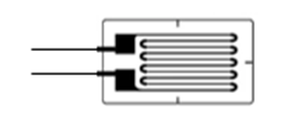
The gauge is attached to the structure under test using a special adhesive. As the structure is stressed, the gauge resistance, measured across the two lead wires, increases (when tensioned) or decreases (when compressed).
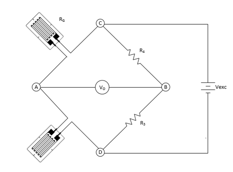
The resistance is usually measured using a Wheatstone bridge circuit. The bridge circuit will look like this:
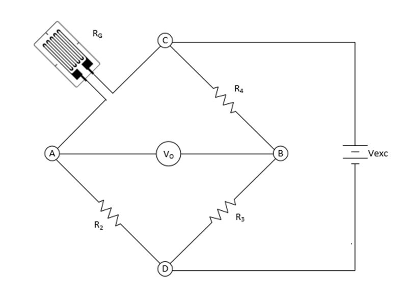
In this example, only a single strain gauge (RG) is to be measured, known as a quarter-bridge circuit. The other resistors in the bridge (R2, R3 and R4) are known as completion resistors and are selected to match the nominal resistance of the gauge. For Prosig systems, this bridge completion is supplied internally by the data acquisition system.
The bridge circuit requires an accurate excitation voltage (Vexc) applied across it (at points C and D in the diagram), and any change in resistance as the gauge is stressed results in a bridge imbalance which causes a voltage at VO, which can be measured by a high-accuracy measurement system across points A and B.
Advertisement
COMPLEXITY MADE SIMPLE
From sensors to DAQ to analysis & reporting, Prosig supports your entire measurement chain
Whether you need accelerometers from our colleagues at DJB Instruments, microphones, pressure sensors or something else, Prosig can supply them as part of your system. Or you can use your own. Discover more about the Prosig hardware and software range.
The bridge circuit can effectively be treated as two separate potential divider circuits, one using resistors RG and R2 and the other R3 and R4. From knowledge of potential divider circuits, the voltages at points A and B will be directly proportional to the ratio of the individual resistance values to the sum of their resistances and the excitation voltage. These can be expressed as:
The bridge circuit can effectively be treated as two separate potential divider circuits, one using resistors RG and R2 and the other R3 and R4. From knowledge of potential divider circuits, the voltages at points A and B will be directly proportional to the ratio of the individual resistance values to the sum of their resistances and the excitation voltage. These can be expressed as:

and

Therefore

When the gauge is not stressed, and the completion resistors match the nominal gauge resistance, then:
RG = R2 = R3 = R4
VO will measure zero volts, and the bridge is said to be balanced. As the gauge is stressed, the gauge resistance will either increase or decrease, the bridge will become unbalanced, and VO will become non-zero. Note that the resistance change, and hence voltage change, will be very small, and the voltage is usually measured in millivolts and may require amplification to achieve the necessary accuracy.
The unit change in resistance of the gauge is related to the strain by the gauge factor, as follows:

Where 

We should also mention another factor that needs to be considered for these measurements, called the bridge factor. The bridge factor (FB) is a number which represents the number of active strain gauges in the bridge circuit. As more active gauges are added, the circuit sensitivity increases. For a quarter bridge, the bridge factor is 1. The bridge factor also affects the resistance to strain relationship and so equation (2) becomes.

Note that the bridge factor represents the number of ‘active’ strain gauges, as sometimes pairs of gauges are fitted at right angles to provide temperature compensation, however only one is active and hence the bridge factor is still 1.
To relate the voltage difference measurements made to the change in resistance at the gauge and hence the strain, we need an accurate way of calibrating the whole system to obtain a sensitivity, usually expressed in units of

See the next part of this series for information on calibrating a bridge circuit using a shunt resistor.
Other configurations of bridge circuits are often used, such as half-bridge, which requires two strain gauges and so will have a bridge factor of 2.
and full-bridge, which uses four strain gauges and hence a bridge factor of 4.

In future posts, we will consider shunt calibration, lead-wire resistance compensation, and consider how we make real-world measurements with strain gauges.
Why not sign up to our newsletter to keep informed of new posts on the blog.
Don Davies
Latest posts by Don Davies (see all)
- Strain Gauge Basics – Part 2 – Shunt Calibration - February 26, 2024
- Bearing & Gearbox Vibration Analysis Using Demodulation Techniques (Part 1) - February 23, 2024
- Strain Gauge Basics – Part 1 - February 9, 2024

It would be interesting to lean more, beyond the basics. Do you have any industrial applications documented? I am looking for a little bit more than basic or published by HBM (or HBK today).
Hi Krystof. Unfortunately, we don’t have any documented customer applications on this topic although we have worked on many such projects. Customers are often cautious about sharing their stories as the problems they are solving are often trade secrets. If you would like to communicate directly, please feel free to reach out to the Prosig team at info@prosig.com