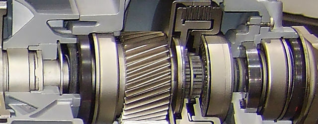
The use of a vibration condition monitoring system for monitoring vibration from large rotating machines fitted with fluid-filled journal bearings such as steam or gas turbines is well understood. Vibration from these components generally falls within the main harmonics or orders of the shaft rotational speed such as 1st, 2nd 3rd or 4th harmonic. Some energy may also exist below the 1st order, called the sub-synchronous component. Most energy exists below 1KHz and so standard displacement probes or velocity transducers are generally fitted. The Prosig PROTOR system collects this data in amplitude and phase form, relative to a ‘once-per-revolution’ phase reference signal, as standard and allows data to be displayed in real-time as mimic diagrams, trend plots, orbit and vector displays.
(more…)


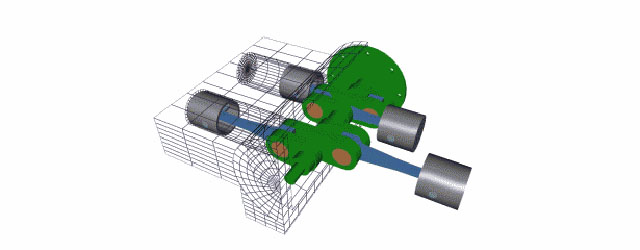


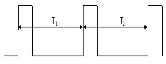
 Knowing how to measure torsional vibration is of key importance in the area of vehicle development and refinement. The main contributory source is the engine where periodically occurring combustion cycles cause variation in the crankshaft rotary vibration. This vibration is transmitted to and modified further by other components in the powertrain such as the gearbox and by other equipment driven off the drive belt or chain. Additional torsional vibrations are also likely to appear downstream at the drive shafts and wheels.