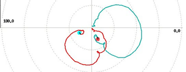
Noise & Vibration Analysis: Back To Basics
Sometimes it doesn't hurt to revisit some of the basic building blocks that form the foundation of what we do. And so we have gathered together a few of our…
Picture the scenario; you have captured some noise & vibration data from a rotating machine. Typically, this might be noise in a vehicle cabin, but could have been anything from…
So you've got some noise and/or vibration data from a rotating machine, but no speed information. Surely that means you can't analyse against speed or do any order analysis, right?…
When performing frequency analysis of vibration data for any application the resultant spectrum has both amplitude and phase components, therefore the phase component represents half of the information available and…
When monitoring vibration on large gas or steam turbines and generators with fluid-film bearings, the relative movement of the shaft within the bearing is typically measured by a pair of…
When using vibration data, especially in conjunction with modelling systems, the measured data is often needed as an acceleration, as a velocity and as a displacement. Sometimes different analysis groups require the measured signals in a different form. Clearly, it is impractical to measure all three at once even if we could. Physically it is nigh on impossible to put three different types of transducer in the same place.
In a recent article we described how the Prosig P8000 hardware and DATS software had been used to help Dalmeny Racing diagnose a problem with an exhaust bracket on their Formula Ford racing car. Whilst the car was instrumented for structural tests on the exhaust the opportunity was taken to carry out a simple automotive noise test. It was felt that these would provide some useful “real world” data as well as maybe providing some extra information regarding the exhaust bracket failure. After analysing and animating the hammer data it became clear that the engine runup data wouldn’t be needed. However, it was decided that some analysis should be carried out to see if the noise and vibration data backed up the conclusions of the other tests.
It is sometimes necessary to perform high pass filtering to eliminate low frequency signals. These may arise for instance from whole body vibrations when perhaps our interest is in higher frequency components from a substructure such as an engine or gearbox mounting. The vibration levels are speed sensitive and the usual scheme is to record a once per revolution ‘tacho’ signal with the vibration data. The tacho signal, which ideally is a nice regular pulse train, is processed to find rotational speed and hence to select which part of the vibration signal is to be frequency analyzed. The most common form of analysis is a waterfall type such as shown below.