When working with audio signals a common requirement is to be able to equalise, cut or boost various frequency bands. A large number of hardware devices on the market provide this capability. The key aspect is that such filters are able to control bandwidth, centre frequency and gain separately. There are broadly two classes of filter used, a “shelving” filter and an “equalising “filter (also known as a “peak” filter). A shelving filter is akin to low pass and high pass filters. An equalising filter is like a bandpass or band reject filter.
For sound quality replay and similar the interest is in equalising filters, specifically in conjunction with removing narrow band resonances our, when dealing with rotating machines, with removal of orders. Actually it is not necessarily the removal of an order but its reduction, or increase, by a specific amount (gain).
The basic component of an equalising filter is an All Pass filter used in a feedback loop. Equalising filters could be based upon standard filters such as Butterworth, Chebyshev and similar. However, experience in audio reconstruction suggests that a more “rounded” filter characteristic is better for audio replay. Accordingly a software version of a standard audio equalising filter has been implemented in DATS. The initial version allows simple band reject (cut) and band increase (boost) by setting the dB gain as negative for cut and positive for boost. The bandwidth and centre frequency are specified independently.
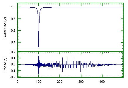
Another aspect caused by filtering is the phase of the output signal. The software allows a choice of “phaseless” or standard filtering. The results for a typical set of values (gain = -10 dB, bandwidth =4Hz) are shown below. In this example the cut filter gives a +/- 30 degrees of phase change. The phaseless implementation reduces this to less than +/- 0.2 degrees.


Order Tracking
A major use of the equalising filter is in enhancing or cutting orders by a specific amount. For example it then becomes possible to consider what a signal sounds like if a particular order was reduced by N dB.
In the example below we have used the standard run down dataset and reduced first order by 6dB. We used one tacho pulse per rev.
After equalising the original time history both signals were waterfall analysed and first order extracted. The results are shown below.

The 6dB reduction is clearly seen. The ratio (black line) between the two order cuts should be a constant, which it is except at rapid rates of change of the order. Even there the variations are generally within +/- 1dB.
Dr Colin Mercer
Latest posts by Dr Colin Mercer (see all)
- Data Smoothing : RC Filtering And Exponential Averaging - January 30, 2024
- Measure Vibration – Should we use Acceleration, Velocity or Displacement? - July 4, 2023
- Is That Tone Significant? – The Prominence Ratio - September 18, 2013


