The intention of this article is not to present any new scientific theories or ground breaking techniques, but to introduce new users to hammer impact testing and remind seasoned technicians of a method of how to calibrate an impact hammer and/or verify the calibration of an instrumented impact hammer (excitation transducer) and an accelerometer (response transducer) pair.
The reader’s imagination can expand on these ideas to use other excitation techniques to calibrate excitation/response transducers as their needs dictate.
Everyone involved in vibration testing, and indeed every good science student, is aware of Newton’s Second Law of motion…
Force = Mass x Acceleration
When performing any testing to measure the frequency response function (FRF) of a structure, this is the basis of all modal testing. Essentially the FRF is the implementation of the second law of motion and is typically expressed as response/excitation. There are several formulations of this which include
- Accelerance (or Inertance) = response acceleration per unit force (A/F)
- Mobility = response velocity per unit force (V/F)
- Compliance (or Receptance) = response displacement per unit force (D/F)
There are other representations, but typically for modal hammer impact calculations the Accelerance (A/F) is used.
What is acceleration divided by force (A/F) equal to? It is the reciprocal of the dynamic mass of the structure between the measured points. If a solid mass structure (block of metal) is impacted at the same point where the response is measured (driving point measurement), any resonances of the structure will typically be higher in frequency than those of interest of most structures. So, below the first structural mode of the test specimen the value of the FRF will be “flat” over a wide frequency range and will be equivalent to the reciprocal of the actual mass of the specimen. There will also be “low” frequency resonances which are the rigid body modes of the structure which will be dependent on how the mass is supported or suspended.
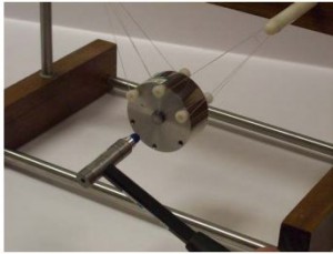
The Modal Shop has a product (model 9155D – 961) that uses this theory to calibrate an impact hammer with a known mass and a calibrated accelerometer (see Figure 1). However, even if the actual sensitivities of the accelerometer and the hammer are not known, the ratio of the sensitivities of these two transducers can be determined to give the actual mass of the block of metal.

The elaborate suspension system of this known mass minimizes rigid body modes of this suspended mass.
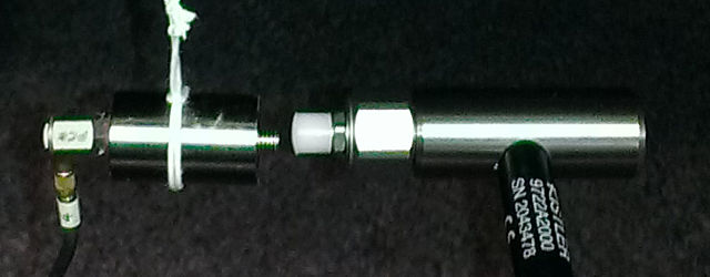
I did not have access to this fancy system, but I wanted to check the sensitivities of my impact hammer and response accelerometer. I performed a very simple test on a known mass of 57 grams I had in the laboratory using an impact hammer (nominal 2.5 mV/N) and an accelerometer (nominal 1 mV/m/sec2). By placing the response accelerometer on one end of the mass, and impacting on the other side of the mass, Since the mass is a solid piece of steel any structural resonances will be well above the frequency range of interest for this calibration consequently there will be no anti-nodes between the excitation and response points. This will essentially be a driving point measurement.

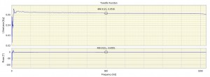
The FRF results in DATS software are saved in Real-Imaginary format, consequently I wrote a simple DATS worksheet to take the reciprocal of the saved FRF, change the units from N/m/sec2 to kg (since 1 newton = 1 kg*m/sec2 ), and convert the data format to Magnitude-Phase. This worksheet is shown in Figure 3.

The results I obtained confirmed both the hammer force transducer and the accelerometer were in good working order and the nominal sensitivities of the transducers were quite close.

For more accurate results, the mass of the accelerometer and cable plus the mass of the hammer tip should be taken into consideration. Any changes to the measurement system such as changing the mass of the impact hammer would suggest this calibration test be re-confirmed.
So, in conclusion, for the purposes of my testing, I was pleased with the results and I was able to continue customer tests with confidence.
Find out more about Hammer Impact Testing…
And, of course, if you need a system to measure and analyse hammer impact or modal data then please take a look at our offerings…
John Mathey
Latest posts by John Mathey (see all)
- Exhaust Vibration Measurement – A Case Study - March 11, 2016
- What Is Amplitude Quantization Error? - January 27, 2016
- Creating An End of Line Vibration Test System - February 25, 2015


Hi John,
Many thanks for the article, its really interesting and useful particularly people like me working on the experimental modal analysis. I need some more elaboration from you to understand the argument you claimed that ‘The elaborate suspension system of this known mass minimizes rigid body modes of this suspended mass’. Could you please kindly explain me if possible how and why it is the case for the particular suspension method.
I really appreciate your valuable time on this.
Thank You,
Kind Regards,
Lavan.
A long time Prosig customer sent us this video of a similar measurement setup, but on a somewhat larger scale…
https://www.youtube.com/watch?v=ktFKT4WYBY0
Pingback: Hammer Testing: Completely free or completely constrained? - Prosig