

We are often asked what noise floor & dynamic range actually are. Most engineers are probably familiar with or have come across the decibel or dB as a unit of measurement. Its most common use is in the field of acoustics, where it is used to quantify sound levels. However, as explained in this article, it is also useful for various measurements in other fields, such as electronics and communications.
One particular use of dB is to quantify the dynamic range and accuracy of an analogue to a digital conversion system. This applies to Prosig’s hardware range, where the noise floor, dynamic range and resolution are all specified in terms of dB.
Decibel (dB)
The decibel is a logarithmic measurement unit that expresses a physical quantity’s magnitude relative to a reference level. It is a dimensionless unit since it expresses a ratio of two quantities having the same units.
Definition
A decibel is used for the measurement of power or intensity. The mathematical definition is the ratio (


When considering amplitude levels, the power is usually estimated to be proportional to the square of the amplitude and so the following can be used:

or

Since the decibel is a logarithmic quantity, it is especially good at representing values that range from very small to very large numbers. The logarithmic scale approximately matches the human perception of both sound and light.
Like all logarithmic quantities, it is possible to multiply or divide dB values by simple addition or subtraction.
Decibel measurements are always relative to given reference levels and can therefore be treated as absolute measurements. That is, if a particular reference value is known then the exact measurement value can be recovered from one of the equations shown above.
The dB unit is often qualified by a suffix which indicates the reference quantity used, some examples are provided in the following section.
Applications
The decibel is commonly used in acoustics to quantify sound levels relative to a reference. This may be to compare two sound sources or to quantify the sound level perceived by the human ear. The decibel is particularly useful for acoustic measurements since for humans the ratio of the loudest sound pressure level to the quietest level that can be detected is of the order of 1 million. Furthermore, since sound power is proportional to the pressure squared then this ratio is approximately 1 trillion.
For sound pressure levels, the reference level is usually chosen as 20 micro-pascals (
Note that since the most common usage of the decibel unit is for sound pressure level measurements it is often abbreviated to just dB rather than the full dB(SPL).
The common decibel units used in acoustics are:
| dB(SPL) | Sound Pressure Level. Measurements relative to 2×10⁻⁵ Pa. |
| dB(SIL) | Sound Intensity Level. Measurements relative to 10-12 W/m2 which is approximately the level of human hearing in air. |
| dB(SWL) | dB Sound Power level. Measurements relative to 10-12 W. |
The human ear does not respond equally to all frequencies (it is more sensitive to sounds in the frequency range from 1 kHz to 4 kHz than it is to low or high frequency sounds). For this reason sound measurements often have a weighting filter applied to them whose frequency response approximates that of the human ear (A-weighting). A number of filters exist for different measurements and applications, these are given the names A,B,C and D weighting. The resultant measurements are expressed, for example, as dBA or dB(A) to indicate that they have been weighted.
In electronics and telecommunication, the decibel is often used to express power or amplitude ratios in order to quantify the gains or losses of individual circuits or components. One advantage of the decibel for these types of measurements is that, due to its logarithmic characteristic, the total gain in dB of a circuit is simply the summation of each of the individual gain stages in dB.
In electronics the decibel can also be combined with a suffix to indicate the reference level used. For example, dBm indicates power measurement relative to 1 milliwatt. The following are some common decibel units used in electronics and telecommunications.
| dBm | Power measurements relative to 1mW |
| dBW | Power measurements relative to 1W. Note that LdBm = LdBW + 30 W/m2 which is approximately the level of human hearing in air. |
| dBk | Power measurements relative to 1kW.Note that LdBm = LdBk + 60 |
| dBV | Voltage measurement relative to 1V – regardless of impedance. |
| dBu or dBv | Voltage relative to 0.775V and is derived from a 600 Ohm dissipating 0dBm (1mW). |
| dBµ | Electric field strength relative to 1µV per meter. |
| dBJ | Energy relative to 1 joule. Used for spectral densities where 1 Joule = 1 W/Hz |
[Further Reading: High Dynamic Range – Fact or Fiction? ]
Examples
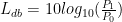
If the numerical value of the reference is undefined then the decibel may be used as a simple measure of relative amplitudes. As an example, assume there are two loudspeakers, one emitting a sound with a power P1 and a second one emitting the same sound at a higher power P2. Assuming all other conditions are the same then the difference in decibels between the two sounds is given by:

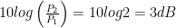
If the second speaker produces twice as much power than the first, the difference in dB is
If the second had 10 times the power of the first, the difference in dB would be

If the second had a million times the power of the first, the difference in dB would be

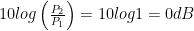
Note that if both speakers produce the same power then the difference in dB would be
This illustrates some common features of the dB scale irrespective of the measurement type:
- A doubling of power is represented approximately by 3dB and a doubling of amplitude by 6dB.
- A halving of power is given by -3dB and a halving of amplitude by -6dB
- 0dB means that the measured value is the same as the reference. Note that this does not mean there is no power or signal.
Noise floor
Any practical measurement will be subject to some form of noise or unwanted signal. In acoustics, this may be background noise, or in electronics, there are often things like thermal noise, radiated noise or other interfering signals. In a data acquisition measurement system, the system itself will actually add noise to the signals it is measuring. The general rule of thumb is: the more electronics in the system the more noise imposed by the system.
In data acquisition and signal processing the noise floor is a measure of the summation of all the noise sources and unwanted signals generated within the entire data acquisition and signal processing system.
The noise floor limits the smallest measurement that can be taken with certainty since any measured amplitude cannot on average be less than the noise floor.
In summary, the noise floor is the level of background noise in a signal, or the level of noise introduced by the system, below which the signal that’s being captured cannot be isolated from the noise.

As shown in Figure 1 the noise floor is better than -120 dB.
Figure 2 shows that only signals above the noise floor can be measured with any degree of certainty. In this case, the signal level of -100dB at 20KHz could be measured. If, however, the noise floor increased above the -120dB level, then it would become more difficult to measure this signal.
For example, the human ear can hear a very low sound, such as a pin drop or a whisper. However, this is only possible if the noise floor or background noise of the particular environment is very low, such as in a soundproof or quiet room. Hearing or discriminating such low levels in a noisy room would not be possible.

Various techniques are employed by the Prosig data acquisition system in order to ensure that the noise floor of the equipment is kept as low as possible. These include signal-processing functions as well as practical features such as the ability to disable cooling fans during acquisition scans.
[Further Reading : Relative signal levels of a sinusoid with and without background noise ]
Dynamic range, noise floor and resolution
Dynamic range is a term used to describe the ratio between the smallest and largest signals that can be measured by a system.
The dynamic range of a data acquisition system is defined as the ratio between the minimum and maximum amplitudes that a data acquisition system can capture.
In practice most Analogue to Digital Converters (ADC) have a voltage range of ± 10V. Sometimes amplification may be applied to signals before they are input to an ADC in order to maximize the input voltages within the available ADC range.
The resolution of a measurement system is determined by the number of bits that the ADC uses to digitise an input signal. Most ADCs have either 16-bit or 24-bit resolution. For a 16-bit device, the total voltage range is represented by 216 (65536) discrete digital values. Therefore the absolute minimum level that a system can measure is represented by 1 bit or 1/65536th of the ADC voltage range. For a system with a voltage range of ±10V then the smallest voltage that the system can distinguish will be:
20 / 65536 = 0.3 mV
In decibels this dynamic range is therefore expressed as:
20 Log10 (65536) = 96dB
Therefore for a 16-bit ADC the dynamic range is 96dB. Using the same calculations the dynamic range of a 24-bit ADC is 144dB.
The noise floor of a measurement system is also limited by the resolution of the ADC system. For example, the noise floor of a 16-bit measurement system can never be better than -96dB and for a 24-bit system the lower limit is limited to -144 dB. In practice, however, the noise floor will always be higher than this due to electronic noise within the measurement system.
Modern data acquisition systems, such as the Prosig Solo, Tetrad or Hyper12, employ a number of sophisticated digital signal processing techniques to improve the amplitude resolution and thereby allow low amplitude data, such as noise floor signals, to be measured with greater precision and with greater accuracy.
[Post edited Jan 2024]
James Wren
Latest posts by James Wren (see all)
- What Are dB, Noise Floor & Dynamic Range? - January 12, 2024
- How Do I Upsample and Downsample My Data? - January 27, 2017
- What Are Vibration, Torsional Vibration & Shaft Twist? - November 8, 2016


Nice article explaining in a concise and effective way some of the concepts linked with the noise floor in a given measurement. I find it useful in general and, particularly, for srudents approaching the fascinating field of expeimental modal analysis obviously linked with the quality of acquired data. Thanks.
basic but important concepts, the author gave them in a way easy for almost anyone to understand as well as concise and correct. new comwers will feel warmhearted and kind, while engineers can verify whether the concepts in Prosig has a little special meaning.
Before this article,I suspected that the Prosig’s dynamic range maybe almost the same as spurious free dynamic range which often given out in other ADC device, now i realized that prosig doesn’t use this parameter. thnks.
P8004 specification, ADC 24bits(total range 144dB), Nioise Floor -120dB, Dynamic Range 102dB.
Can i say it as following way ?
compare to full range, if signal level below -120dB, P8004 can not distinguish it; if signal level betweetn -120dB and -102dB, P8004 can see the signal, but cannot measure it with accuracy; only if signal level above -102dB, P8004 can do its measurement with enough accuarcy.
if the saying is ok, then there is an 8dB gap, between P8004’s perceptive and capable, can i know yr basic argument of this 8dB, or what cause this 8dB and why it is 8dB basicly.
If any amplifier used in P8004, and in ADC, maybe nonlinearity will cause harmonic peaks, Have the higher order peaks level already been deducted from the range? now, my problem is I need to know whether P8004’s dynamic range already cover this issue because other co. product often give out the SFDR parameter. customers need a comparasion between products to be convinced.
thanks in advance.
Mr Xiochang,
Thank you for your comments.
You are correct, we at Prosig are as honest and straight forward as possible. We strongly believe it is bad idea to confuse our customers with numbers that are not correct. We are after all English gentlemen, we pride ourselves on our honesty and our good relationships with our customers.
Spurious Free Dynamic Range is defined as ‘The difference between the rms amplitude of the input signal and the peak on the spurious signal’. So in this case the Spurious Free Dynamic Range (SFDR) is the difference between the RMS of the input signal and the peak of the Noise created by the system itself.
We call this the Noise Floor.
The P8000 series has up to a -120 dB noise floor, depending upon which P8000 input card you purchase.
Mr Xiochang,
Again we thank you for your comments.
I do not think it is possible to add or take away from each other the Dynamic Range and the Noise floor. They are in fact different quantities.
All our stated values are actual measured quantities, not mathematically calculated values. These are the real values you get in the real world with a P8000 series.
I’ll try to explain, the P8000 series, in this case has the following characteristics,
Noise Floor = -120dB
Dynamic Range = 105dB
Noise floor or Spurious Free Dynamic Range.
This means in straight forward terms that if the signal your trying to measure is below -120dB you will not be able to measure it with the P8000. This is because it would, at any particular frequency, be obscured by the noise introduced by the P8000 itself.
Dynamic Range or Signal to Noise Ratio (SNR)
The Signal to Noise Ratio, sometimes called Signal to (Noise and Distortion) Ratio is defined as ‘The ratio of the rms value of the actual input signal to the rms sum of all the other spectral components below the Nyquist frequency, including harmonics but excluding dc.’
This means the Dynamic Range is the ratio of the rms of the input signal to all of the components including noise below the Nyquist frequency.
Or more simply, the Dynamic Range is the voltage of the Input signal divided by the voltage from all components already present in the system, this includes the harmonics from the input signal.
So you can see that the Noise Floor and the Dynamic Range are not directly compatible.
The Noise floor is the lowest level at which the P8000 can measure a signal at any particular frequency.
The Dynamic Range is the ratio of the largest input the P8000 series can measure to the smallest signal that is not obscured by all the components present in the system, including the frequency content of all of the noise and any other components present.
thanks Mr.Wren.
“The ratio of the rms value of the actual input signal to the rms sum of all the other spectral components below the Nyquist frequency, including harmonics but excluding dc”. I questioned why that the Noise Floor and the Dynamic Range are not directly compatible, here u have given me a clear answer, thanks.
Ordinary ADC/DAC says:
SFDR (Spurious Free Dynamic Range) indicates in dB the ratio between the powers of the converted main signal and the greatest undesired spur.
SNR (Signal to Noise Ratio)indicates in dB the ratio between the powers of the converted main signal and the sum of the noise.
SNDR (Signal to Noise and Distortion Ratio) indicates in dB the ratio between the powers of the converted main signal and the sum of the noise and the generated harmonic spurs
I agree with Mr.Wren “Dynamic Range or Signal to Noise Ratio (SNR)”. I see here yr SNR means the SNDR, u already gave yr definition in yr anawer while deliberately avoiding further definition details. Do u agree with this saying: Dynamic range is the reciprocal of the smallest value of SNDR, after converted off the dB?
u said “Noise floor or Spurious Free Dynamic Range”, if u mean that Noise floor directly consponds to Spurious Free Dynamic Range, i doubt it. because under the above definitions, SFDR depends on the biggest harmonic peak, it considers the linearity of the system. Harmonic peaks are signal dependent value, while Noise floor’s main component is thermal noise.
I think maybe it will be better to give out both the Dynamic Range and SFDR in prosig’s P8000 specification, not only Dynamic Range parameter, at least it will be convienent to different users, how do u think about this? maybe u can only give me a personal opinion, for me that’s ok .
Hello Again Mr Xiochang,
I do agree with your points, very much so, in the P8000 product literature we do provide a dynamic range and a separate noise floor. Which I believe is your point.
the definition of the dB is not complete, strictly speaking not correct, as most users are not aware (may be you at Prosig too!) that the basic unit is the Bell, abreviated B. The Bell is defined as the logarithm based 10 of the ratio of a power divided by a reference power: B = log(P/Pref).
Since the Bell is giving to small values for common uses, the deciBell (dB) is used, which is one tens of a Bell, and therefore the values expressed in dB are 10 times higher that those in Bell: dB = 10*log(P/Pref).
Note that dB is strictly speaking not an unit, only the Bell is one. dB is like dm (one tens of a meter), dl (one tens of a liter)…
So a sound Level of 70,6 dB is equal to 7,06 B!
Hello Mr Weiler,
Thanks for adding to the blog, you are quite correct of course in all your points.
Thank you for reminding us all.
Hi, thanks for a great straightforward explanation of the basics of the terminology and concepts. Just one thing; in the section for dynamic range, you have typed:
20 Log10 (1 / 65536) = 96dB
Should it not be:
20 Log10 (65536) = 96dB
Thanks again.
Dear Bharat, Thank you for your kind compliments and for pointing out our mistake. It seems an error was made when transcribing the original article onto the blog. This has now been corrected. Thank you again.
Could you please elaborate how could I measure the signal if it is less than the noise floor.
I work in EMC testing and we use. ROHDE & SCHWARZ receiver, the noise floor is itself 20dB.Are there any chances for improving it?
Hello Dikshith,
Thank you for asking a question on our blog.
We understand your issue and sympathise with you, we come across this subject time and time again.
You basically have two options to reduce the noise floor of your equipment,
I would suggest you start with option 2 and consider option 1 if you have no luck with option 2.
In summary you should be able to get the noise level well down from your current levels and measure signals which are currently being obscured by the noise.
Very nice article. I hope to add a point of clarity to noise floor. As was pointed out, noise floor, usually expressed in Vrms, is the sum of all noise sources and it limits the level of signal that can be accurately measured. However, noise floor should be looked at differently in the time and frequency domains. In the frequency domain, it is possible to have a signal that is 20 dB above the FFT noise floor (depends on size of FFT) yet the signal itself may have an RMS level that is below the RMS of the total noise. Thus it is possible for a signal that cannot be seen or detected in a time domain acquisition, to be easily seen in a frequency domain plot.
Hi Steve,
Thank you for posting on our blog, and thank you for such a concise and clear post.
You are indeed quite correct, thank you for sharing your point with us all, please feel free to post other comments if you have them.
Very useful article
Hi Puna,
Thanks for posting on our blog, we are pleased that you have found the article useful.
Thank you!
Please clarify:
16 bit ADC 2Vpp i/p voltage range differential, Resolution is 30.5uV. If my signal range is 1.35 to 1.85V I can level shift it (1.35V ~ 1.85V)- 1.35 = 0V ~0.5V) and have a gain of 4 to match the ADC input range ie 2Vpp.
For this signal condition and single end to differential end conversion noise in signal chain is 100uV.
Can i acquire step size of 30.5uV atleast above 250uV to 2V.
Hello Kumar,
Thank you for posting on our blog.
16 bit will give you potentially 65536 voltage levels.
Across a 2 volt input range that will give you 30.5uV ideally.
The gain you can use will be a factor of the amplifiers and voltage range you have available on your front end, if you say you can ‘level shift’ then you’d be using 0.5V of your ADC range.
Thus if you used a gain of 4 you would be using all of your ADC range.
But this allows no margin of error, as a guide at Prosig we always use a margin of error of 50%, so we would use a gain of 2 with those numbers.
You say your noise is 100uV, so Yes, you could capture from that point up to 2V.
I fear you maybe over simplifying, have you considered anti alias filtering for example? And how do you intend to ‘level shift’?
Thank u James,
So by 50% of error margin will u acquire signal from 1V to 2V.
one more thing in ADC I have a parameter common mode voltage 0.9V, does this help me regarding noise.
Hello Kumar,
No, 50% would be zero to 1V.
Signals are not normally only positive or negative, so we would work on +/- rather than just +.
The common mode is relevant to instrumentation amplifiers, it will not affect the noise level.
Common mode means the difference between the two inputs, so common mode voltage is the maximum voltage, in your case 0.9V.
Pingback: How much havoc is caused by unwanted radio signals? FCC tries to find out – Diashmond
Pingback: How much havoc is caused by unwanted radio signals? FCC tries to find out
Pingback: What sample rate and bitrate should I use for music distribution? | Jamvana
Pingback: Basic Audio Production - week 16 | PCC Classes
Pingback: Gain Staging: Secret to Get Good Levels In Your Mix
Pingback: Noise floor: 3 things you should know - www.djgblogger.com
I hope you see this. I recently (year 2023) saw in the specifications of a renowed brand, that the equipment has 136dB-A dynamic range. Wich i find is an error, since dynamic range is just specified in dB. Am i wrong?