

[An Introduction To Vibration Analysis – Part 2]
Introduction
This post on vibration measurement techniques is the second in our series, introducing vibration analysis. Future posts will continue the exploration of these topics in more detail. Why not sign up for our mailing list and ensure you don’t miss future articles.
Vibrations are ubiquitous phenomena that significantly impact our lives and various industrial applications. Engineers can diagnose machinery problems by measuring vibrations, validate simulation models, and ensure comfort and safety in automotive, aerospace, and industrial applications. The following guide delves into the vibration measurement techniques used to measure vibrations, offering a comprehensive overview for novice and seasoned engineers.
1. Time-Domain Measurement
The simplest and most intuitive way to measure vibrations is in the time domain, capturing the vibration signal as a function of time. Engineers commonly use accelerometers, velocity sensors, or displacement sensors for this purpose. These sensors convert mechanical vibrations into electrical signals, which are then recorded and analyzed using a data acquisition (DAQ) front end.
Applications: Time-domain measurement is highly valuable in fault detection, time-domain analysis, and initial vibration assessment. It’s particularly effective for analyzing transients and non-stationary signals that change over time.
Challenges: Time-domain analysis can be challenging for complex systems or vibrations with overlapping frequencies. It’s often hard to distinguish between multiple vibration sources or identify specific frequency components.
Expanding the Technique: Time-domain analysis involves techniques like time waveform analysis, shock response analysis, and time-frequency analysis. Time waveform analysis provides an instantaneous snapshot of the vibration signal, while shock response analysis studies how systems respond to sudden changes. Time-frequency analysis combines the time and frequency domains, offering a comprehensive view of vibrations.
2. Frequency-Domain Measurement
Frequency-domain measurement is another critical vibration measurement technique. Engineers transform time-domain signals into frequency-domain signals using mathematical tools like Fast Fourier Transform (FFT) or wavelet transform. This process helps in isolating and analyzing individual frequency components.
Equipment: FFT Analyzers are the standard equipment for frequency-domain measurement. They convert time-domain signals into frequency spectra, allowing engineers to identify specific frequencies contributing to the vibration.
Applications: Frequency-domain measurement is essential for identifying natural frequencies, performing modal analysis, and conducting harmonic analysis. It is widely used in the automotive, aerospace, and civil engineering industries.
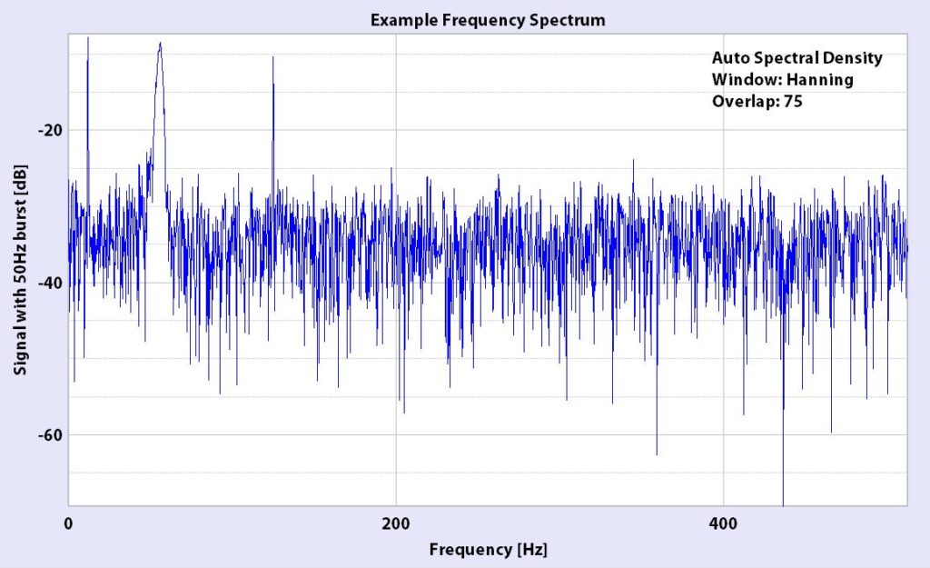
Challenges: Frequency-domain measurement requires precise windowing techniques and adequate sampling rates. Ensuring accurate results demands a thorough understanding of signal processing and sampling theory.
Expanding the Technique: Frequency-domain analysis is further divided into various approaches, including Power Spectral Density (PSD) analysis, cross-spectral density analysis, and transfer function analysis. PSD analysis provides a snapshot of the vibration’s energy distribution across frequencies. Cross-spectral density analysis helps identify correlations between two signals, while transfer function analysis studies the relationship between input and output signals.
3. Modal Analysis
Modal analysis is a comprehensive technique that extracts a system’s natural frequencies, damping ratios, and mode shapes. These parameters are crucial for understanding system behaviour, improving the design, and ensuring stability under various operating conditions.
Equipment: Modal analysis typically involves using impact hammers, shakers, and modal analyzers. Impact hammers provide controlled excitation, while shakers offer a range of excitation profiles, including random, sinusoidal, and chirp signals. Modal analyzers process the recorded data, extracting mode shapes and natural frequencies.
Applications: Modal analysis finds applications in structural dynamics, system identification, and validation of finite element models. It helps engineers design robust structures, improve damping, and reduce resonance-related issues.
Challenges: Properly exciting a system and correlating modes requires experience and careful execution. Ensuring all modes are identified and distinguishing between closely spaced modes can be challenging.
Expanding the Technique: Experimental modal analysis (EMA) and operational modal analysis (OMA) are two main approaches within modal analysis. EMA involves exciting the system with known forces, while OMA relies on natural excitations like wind or traffic loads. Both approaches provide valuable insights into system behaviour, but the choice depends on the application and available equipment.
4. Acoustic Emission
Acoustic emission (AE) is a passive measurement technique that detects stress waves produced by sudden structural changes, such as crack formation, internal defects, or friction. By analyzing AE signals, engineers can assess the material’s condition and monitor ongoing processes.
Equipment: AE systems typically include piezoelectric sensors, amplifiers, and high-speed data acquisition systems. The piezoelectric sensors convert mechanical stress waves into electrical signals, which are then amplified and recorded for analysis.
Advertisement
COMPLEXITY MADE SIMPLE
From sensors to DAQ to analysis & reporting, Prosig supports your entire measurement chain


Whether you need accelerometers from our colleagues at DJB Instruments, microphones, pressure sensors or something else, Prosig can supply them as part of your system. Or you can use your own. Discover more about the Prosig hardware and software range.
Applications: Acoustic emission finds applications in condition monitoring, non-destructive testing, and early fault detection. It’s widely used in oil and gas, aerospace, and civil infrastructure industries.
Challenges: Differentiating between signals from defects and background noise demands careful analysis. AE signals can be affected by sensor placement, material properties, and environmental conditions.
Expanding the Technique: AE analysis involves signal filtering, waveform analysis, and time-frequency analysis. Signal filtering helps separate relevant signals from noise, while waveform analysis identifies specific AE events. Time-frequency analysis provides insights into the signal’s evolution over time and frequency.
5. Laser Doppler Vibrometry
Laser Doppler Vibrometry (LDV) is a non-contact measurement technique that measures vibrations by analyzing the frequency shift of a laser beam reflected off a vibrating surface. LDV offers high precision and sensitivity, making it suitable for various applications.
Equipment: LDVs consist of a laser source, optics for beam shaping and focusing, and a detector for measuring the Doppler shift. Modern LDVs often include advanced features like scanning capabilities and multiple channels.
Applications: LDV is used for non-contact vibration measurement, analysis of tiny components, and high-frequency measurements. It is especially valuable in microelectronics, biomedical engineering, and automotive testing industries.
Challenges: Surface properties can affect measurements, and the equipment is generally more expensive than contact-based sensors. Proper alignment and focusing are crucial for accurate results.
Expanding the Technique: Advanced LDV techniques include 3D scanning vibrometry, time-averaged vibrometry, and stroboscopic vibrometry. 3D scanning vibrometry measures vibrations in three dimensions, providing a complete view of the object’s motion. Time-averaged vibrometry visualizes vibration patterns, while stroboscopic vibrometry captures transient phenomena.
6. Shock Response Spectrum Analysis
Shock Response Spectrum (SRS) analysis is a technique that evaluates a system’s response to shocks, replicating real-world conditions like earthquakes, blasts, or impacts. SRS provides a frequency-based representation of the system’s shock response, helping engineers design for extreme events.
Equipment: Shock test machines and accelerometers are typically used for SRS analysis. Shock test machines produce controlled shocks, while accelerometers measure the system’s response.
Applications: SRS analysis is used in earthquake engineering, aerospace component testing, and durability assessment. It helps engineers design structures and components to withstand extreme shock events.
Challenges: Setting realistic test conditions and interpreting complex response spectra can be challenging. Engineers must consider factors like shock duration, magnitude, and waveform shape.
Expanding the Technique: SRS analysis involves time-history analysis, pseudo-velocity shock spectrum analysis, and shock qualification testing. Time-history analysis studies the system’s time-domain response, while pseudo-velocity shock spectrum analysis provides insights into the system’s maximum response velocities. Shock qualification testing ensures that components meet industry-specific shock resistance standards.
7. Order Tracking
Order tracking is a specialized technique for analysing vibrations concerning a system’s operating speed. This method is crucial for machinery with variable speeds, like engines, turbines, and compressors.
Equipment: Order-tracking analysis requires tachometers, accelerometers, and specialized order-tracking analyzers. Tachometers measure the system’s rotational speed, while accelerometers capture the vibration data. Order tracking analyzers process the data and present the results concerning the operating speed.
Applications: Order tracking is used for rotating machinery analysis, quality control, and operational optimization. It’s particularly valuable in automotive, aerospace, and power generation industries.

Challenges: Accurate speed measurements and phase calculations are essential for proper order tracking analysis. Engineers must ensure proper sensor placement and calibration to achieve reliable results.
Expanding the Technique: Order tracking involves techniques like Campbell diagrams, waterfall plots, and colour or spectral maps. Campbell diagrams visualize how natural frequencies change with speed, highlighting potential resonances. Waterfall plots display vibration data at different speeds, revealing trends and patterns. Spectral maps show how vibration amplitudes change with speed and frequency, providing a comprehensive view of system behaviour.

8. Vibration Control and Isolation
After measuring vibrations, controlling or isolating them is often essential to enhance system performance, improve comfort, or reduce noise. Vibration control and isolation involve various strategies to mitigate unwanted vibrations.
Techniques: Vibration control techniques include passive damping, active vibration control, and base isolation. Passive damping relies on materials and geometries to absorb vibrations, while active control uses sensors, actuators, and control algorithms to counteract vibrations. Base isolation decouples the system from external vibrations, preventing their transmission.
Applications: Vibration control and isolation are crucial for vibration-sensitive equipment, seismic isolation, and machinery noise reduction. These techniques find applications in semiconductor manufacturing, civil engineering, and automotive industries.
Challenges: System-specific solutions are needed, as each application has unique requirements. Active control requires advanced algorithms, high-quality sensors, and actuators, making it more complex and costly than passive techniques.
Expanding the Technique: Advanced vibration control techniques include adaptive control, hybrid control, and tuned mass dampers. Adaptive control adjusts the control parameters based on real-time measurements, optimizing performance. Hybrid control combines passive and active techniques, offering the best of both worlds. Tuned mass dampers are mechanical devices that counteract vibrations by moving out of phase with the system.
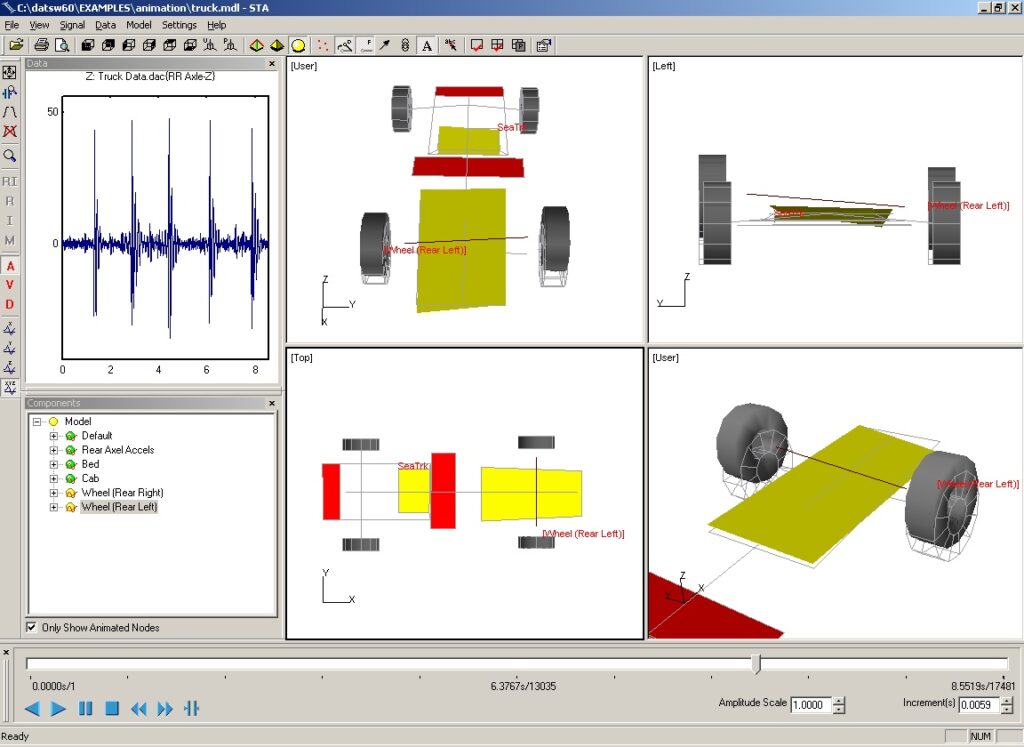
9. Operational Deflection Shape Analysis
Operational Deflection Shape (ODS) analysis is a technique used to visualize and interpret vibration patterns of operating machinery and structures. Using ODS analysis, engineers can identify the source of vibration issues and optimize their designs.
Equipment: ODS analysis typically involves accelerometers, modal analysis software, and sometimes a 3D scanner. Accelerometers are placed on the system to capture vibration data at multiple points. The software processes the data and generates animations that show the vibration patterns of the system.
Applications: ODS analysis is particularly useful for large structures and complex systems, such as buildings, bridges, and industrial machinery. It helps engineers understand the real-world vibration behaviour of a system, diagnose problems, and validate finite element models.
Challenges: Accurate ODS analysis requires careful sensor placement and high-quality data. Interpreting the results can be challenging, especially for complex systems with multiple vibration sources.
Expanding the Technique: ODS analysis can be further refined with advanced techniques like 3D scanning ODS, which provides a full 3D visualization of the vibration patterns. Modal assurance criterion (MAC) analysis can be used to correlate ODS results with modal analysis results, ensuring accurate interpretations.
10. Rotordynamics Analysis
Rotordynamics analysis is a specialized field of vibration analysis focusing on rotating machinery, like turbines, engines, and compressors. It studies the forces, torques, and vibrations affecting rotating components and helps optimize their performance and reliability.
Equipment: Rotordynamics analysis requires specialized hardware, software, accelerometers, and tachometers. The software simulates rotor behaviour under various conditions, while accelerometers and tachometers capture real-world vibration and speed data for validation.
Applications: Rotordynamics analysis is crucial for ensuring rotating machinery’s smooth and stable operation, preventing critical speed issues, and optimizing bearing design. It’s widely used in power generation, aerospace, and oil and gas.
Challenges: Rotordynamics analysis demands accurate modelling of the rotor system, including bearings, seals, and shafts. Real-world data is needed to validate simulations, and interpreting the results requires a deep understanding of rotor behaviour.
Expanding the Technique: Advanced rotordynamics analysis techniques include cross-coupled stiffness analysis, which studies the interaction between lateral and torsional vibrations, and stability analysis, which assesses the system’s response to disturbances. These techniques help engineers design more robust and reliable rotating machinery.
11. Environmental Vibration Analysis
Environmental vibration analysis assesses the impact of external vibrations on structures, equipment, and human comfort. It involves measuring ground-borne vibrations from sources including traffic, construction, and natural events.
Equipment: Environmental vibration analysis requires geophones, seismometers, and specialized data acquisition systems. Geophones measure ground vibrations, while seismometers capture seismic events. The data acquisition system records and processes the data for analysis.
Applications: Environmental vibration analysis is essential for assessing the impact of vibrations on buildings, infrastructure, and sensitive equipment. It helps engineers design structures that can withstand external vibrations and minimize their effects.
Challenges: Accurate environmental vibration analysis requires careful consideration of factors like soil properties, local geology, and vibration sources. Interpreting the results demands a thorough understanding of vibration transmission and structural dynamics.
Expanding the Technique: Advanced environmental vibration analysis techniques include ground response analysis, which studies how soil layers affect vibration transmission, and microtremor analysis, which assesses seismic vulnerability. These techniques help engineers design structures and foundations to better cope with external vibrations.
Vibration Measurement Techniques – Closing Thoughts
Vibration measurement techniques are both an art and a science, requiring a firm grasp of physical principles, mathematical techniques, and practical knowledge. Each measurement technique offers unique insights into system behaviour and reveals information that can lead to improved designs, enhanced performance, and a better understanding of complex systems.
From time-domain measurements to advanced modal analysis, the world of vibrations is vast and intricate. By choosing the right tools for the right job and carefully considering factors like the type of system, available equipment, and required analysis depth, engineers can unravel the mysteries of vibrations and harness their potential for innovation and problem-solving.
Some Recommended Reads:
- “Vibration Spectrum Analysis” by Steve Goldman: Delve deeper into frequency-domain analysis with this insightful book.
- “Practical Machinery Vibration Analysis and Predictive Maintenance” by Paresh Girdhar and Cornelius Scheffer: A guide for engineers focused on machinery health and maintenance.
- “Modal Testing: Theory, Practice, and Application” by D.J. Ewins: A comprehensive resource on modal analysis.
Feedback and discussions are encouraged in the comment section. Dive deep, analyze thoroughly, and remember – in every oscillation, there’s information waiting to be decoded.
![Read more about the article [Video] A Simple Capture, Analysis and Report (Part 3)](https://blog.prosig.com/wp-content/uploads/2011/06/videoTutorials-640-250-300x117.jpg)

“Exploring vibration measurement techniques provides a comprehensive understanding of monitoring methods crucial for assessing structural integrity and equipment performance.”
“Kudos to the authors for shedding light on the importance of integrated measuring systems in ensuring product quality and consistency.