

The use of strain gauges with Prosig’s data acquisition systems is well understood and has been used in many real-world applications over the years [see What Is A Strain Gauge? by James Wren here on the blog and also available as Strain Gauges Explained in the Prosig Noise and Vibration Measurement Handbook].
The following post is the second part of a series that provides a recap and update to that article.
Shunt Calibration of Strain Gauges
As mentioned in the previous post, in order to relate the measured voltage difference across the bridge circuit to a strain measurement, we need a way of calibrating the system. In most systems, including the Prosig acquisition systems, this is done by including a high-precision shunt resistor across one of the legs in the bridge. For example, the following diagram shows a quarter-bridge circuit with a shunt calibration resistor, RS, across the bridge completion resistor R2.
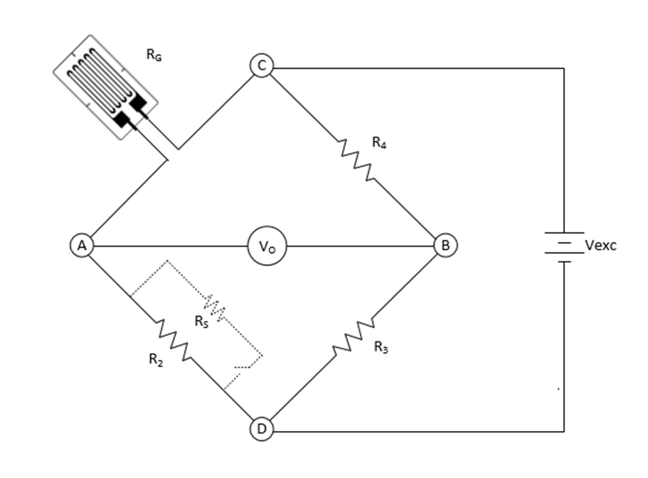
As the shunt resistor (RS) is a known value, its imbalance effect on the bridge can be calculated. By measuring the voltage difference across points A and B with and without the shunt resistor added, we can relate the change in voltage to the change in resistance and hence the strain based on the following equation from the previous post.

The equivalent resistance at R2 when we switch in the shunt resistor in parallel across R2 is given by:

The change in resistance is

or


and so

Advertisement
COMPLEXITY MADE SIMPLE
From sensors to DAQ to analysis & reporting, Prosig supports your entire measurement chain


Whether you need accelerometers from our colleagues at DJB Instruments, microphones, pressure sensors or something else, Prosig can supply them as part of your system. Or you can use your own. Discover more about the Prosig hardware and software range.
Therefore

From equation (3) in the previous post – 
We get


Therefore, the equivalent change in strain, with or without the shunt resistor applied is given by:

By measuring the difference in voltage, 


The voltage difference will be very small and usually measured in mV, the resultant sensitivity will also be very small and so the sensitivity is usually represented in units of 

As an example, for a 120
With an excitation voltage of 10V and we can calculate the voltage difference with and without the shunt resistor applied using equation (1) from the previous post

This gives us the expected
We can check the operation using the above equations to calculate the effective micro-strain when reapplying the shunt resistor with the calculated sensitivity and reading the measured strain. For the above example, the expected strain when the shunt is applied will be 475.73

In future posts, we will consider lead-wire resistance compensation and look at how we make real-world measurements with strain gauges.
Why not sign up to our newsletter to keep informed of new posts on the blog.
Don Davies
Latest posts by Don Davies (see all)
- Strain Gauge Basics – Part 2 – Shunt Calibration - February 26, 2024
- Bearing & Gearbox Vibration Analysis Using Demodulation Techniques (Part 1) - February 23, 2024
- Strain Gauge Basics – Part 1 - February 9, 2024


