As mentioned in our previous article, when performing experimental modal testing of a structure or component using impact (or ping) testing, it is important to consider and verify the validity of any results. A modal analysis is valid if it satisfies several assumptions.
This article considers reciprocity.
Reciprocity Check
Reciprocity means that the transfer function formed from a response measured at point B on a structure and excitation applied at point A is the same as that with the response measured at A and the same excitation applied at B.
This assumption of reciprocity is fundamental when attempting to reduce the number of impact measurements made on a structure.
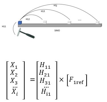
For a multiple input and multiple output system, to complete the impacts tests for all impact points and all response positions we have the transfer function equation [X] = [H] x [F] in matrix form:

Clearly, it is very time-consuming to calculate the whole matrix. If the reciprocity rule is satisfied, Hij = Hji , only half of the transfer function matrix, either upper or lower, needs to be measured due to its symmetry. This is especially useful for transfer path analysis.
The reciprocity rule applied in the hammer test is to ensure that the transfer functions remain the same wherever the reference is chosen.
In general, prior to performing a set of impact tests, the engineer marks on the structure a series of points of where to impact and to where to measure responses. The aim is to calculate transfer functions between the responses and impacts, denoted as Hij, for the i response positions and j impact points.
Normally for a single input multiple outputs (SIMO), multiple input single output (MISO) or single input single output system (SISO) that hammer test is applied on, either i or j is defined as the reference, all the transfer functions are corresponding to this reference.
If the reciprocity rule is satisfied, the transfer functions are the same whatever the way of roving impacts or roving accelerations is chosen for ether SIMO or MISO. The user will benefit from that especially when the testing condition is limited with the number of accelerometers or space to apply an effective impact.
Example: A simple beam structure
This concept is shown below for a simple beam structure:
- Measuring one column of the FRF matrix can be achieved from impacting at a single input position and measuring at multiple output locations. This method is often known as roving response (Figure 2).

2. Measuring one row of the FRF matrix is achieved by multiple impacts and a single measurement location. This is known as roving excitation (Figure 3).

A simple test as shown in Figure 4 below indicates how to check the reciprocity. A test can easily be performed by performing an impact test and impacting at one position and measuring the response at another, then swapping the impact and measurements positions and comparing the transfer functions. In the figure below, the blue and green curves are the transfer functions calculated by swapping the impact and response positions. These two curves match well and prove reciprocity rule holds true.

The efficiency in performing impact testing can be greatly improved if the user has access to multiple accelerometers and a multi-channel data acquisition system. In this case, many responses can be measured simultaneously for a single impact.
If the number of accelerometers or data acquisition channel count is limited, users must either move the accelerometers in batches or rove the impact hammer over all the points to decide to calculate the matrix by row or column.
Careful choice will lead to more accurate results. Basically, moving the accelerometer can affect the dynamic characteristics of the structure. Especially for a lightweight structure and a heavy accelerometer, the influence will be more prominent. The roving impact approach can reduce this mass load influence. However, if the structure’s shape or installation position make for restricted access and make effective hits impractical the roving accelerometer will be the best option.
Make sure you don’t miss the rest of this series. Sign up to our mailing list
Dr Cindy (Xin) Wang
Latest posts by Dr Cindy (Xin) Wang (see all)
- Impact Hammer Double Hit – An Investigation - June 13, 2023
- Some Basic Vibration Signal Qualities - August 17, 2022
- Automated data capture, analysis and reporting - May 10, 2022


